Ink cartridges and ink supply systems

a technology of ink supply system and cartridge, which is applied in the direction of printing, etc., can solve the problems of deteriorating pump sealing, and affecting the sealing effect of the pump

Inactive Publication Date: 2011-06-07
BROTHER KOGYO KK
View PDF20 Cites 14 Cited by
  • Summary
  • Abstract
  • Description
  • Claims
  • Application Information

AI Technical Summary

Benefits of technology

[0010]A need has therefore arisen for ink cartridges and ink supply systems which overcome these and other shortcomings of the related art. A technical advantage of the present invention is to prevent ink leakage from a pump and to supply ink with high reliability. Another technical advantage of the present invention is to separate air bubbles from ink and to prevent air bubbles from staying in the valve accommodating chamber.
[0011]According to an embodiment of the invention, an ink cartridge comprises an ink chamber configured to store ink therein, wherein the ink chamber is defined by at least one wall, and an air layer is formed in the ink chamber between a surface of the ink and at least a portion of the at least one wall, and a pump configured to selectively supply air to the air layer and to draw air from the air layer.
[0012]According to another embodiment of the invention, an ink supply system comprises a first ink tank comprising an ink chamber configured to store ink therein, wherein the ink chamber is defined by at least one wall, and an air layer is formed in the ink chamber between a surface of the ink and at least a portion of the at least one wall, and a pump is configured to selectively supply air to the air layer and to draw air from the air layer, and a second ink tank configured to store ink. The first ink tank and the second ink tank are configured to be in fluid communication with each other.
[0013]According to an embodiment of the invention, an ink cartridge comprises an ink chamber configured to store ink therein, wherein the ink chamber is defined by at least one wall, a side wall having a first opening formed therethrough, a particular wall extending from the side wall toward the ink chamber, having a second opening formed therethrough, a valve accommodating chamber defined by the particular wall and configured to be in fluid communication with an outside of the ink cartridge via the first opening, and to be in fluid communication with the ink chamber via the second opening, a valve accommodated in the valve accommodating chamber, the valve configured to move in the valve accommodating chamber to selectively allow and prevent fluid communication between the valve accommodating chamber and the outside of the ink cartridge via the first opening. The second opening is positioned above both the valve accommodating chamber and the first opening.

Problems solved by technology

Nevertheless, since the pump is provided in the ink supply path, ink may leak from the pump if the pump breaks, the tubing of the pump ages and deteriorates, or the pump sealing deteriorates.
This is because, if some of the ink in the recording head and the tube is left in the valve accommodating portion, air bubbles trapped in the ink may adhere to the valve, which may disturb the movement of the valve.

Method used


Image

  • Ink cartridges and ink supply systems
  • Ink cartridges and ink supply systems
  • Ink cartridges and ink supply systems

Examples


case 52

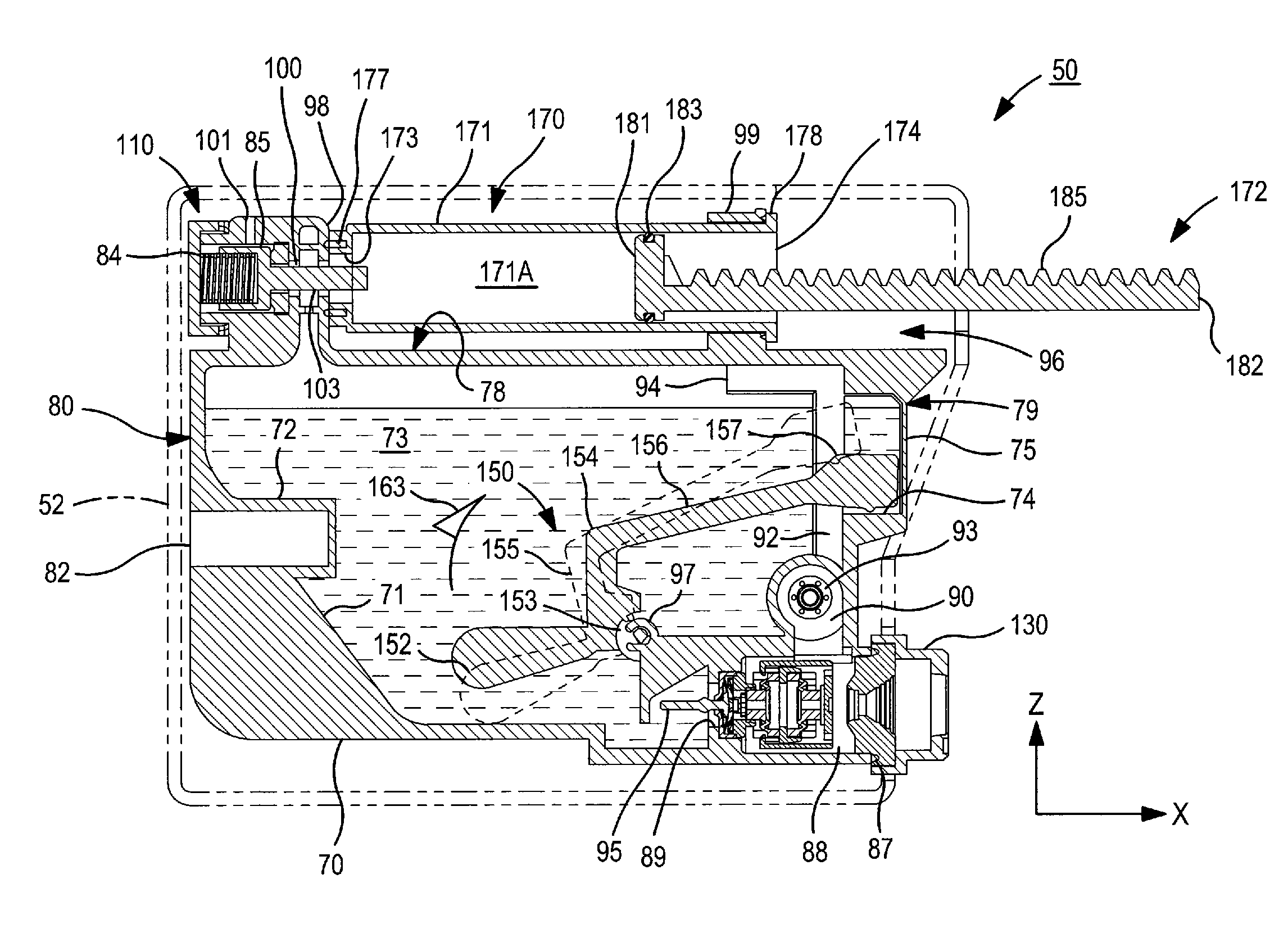
[0047]Case 52 may comprise a first case member 53 and a second case member 54. Case 52 may be configured to be selectively disassembled into first case member 53 and second case member 54 along an X-axis direction when case 52 is positioned as shown in FIG. 3. The shape of first case member 53 may be substantially the same as the shape of second case member 54. Each of first case member 53 and second case member 54 may comprise at least one synthetic resin, and may be manufactured by injection molding.

[0048]Case 52 may comprise a top face 59 and a front face 60. Front face 60 has a first end and a second end, and top face 59 may be connected to the first end of front face 60. Opening 56 may be formed through top face 59, and may extend to front face 60, and may be defined by cut-out portions 61 formed in first case member 53 and second case member 54, respectively. A portion of a rod 182, which will be described in more detail herein, may be positioned in opening 56, and rod 182 may...


PUM


Abstract

An ink cartridge includes an ink chamber configured to store ink. The ink chamber is defined by at least one wall, and an air layer is formed in the ink chamber between a surface of the ink and a portion of the wall. The ink cartridge also includes a pump for selectively supplying air to the air layer and to draw air from the air layer. An ink supply system includes a first ink tank including an ink chamber defined by at least one wall, and an air layer is formed in the ink chamber between a surface of the ink and a portion of the wall. The ink supply system also includes a pump for selectively supplying air to the air layer and to draw air from the air layer, and a second ink tank in fluid communication with the first ink tank.

Description

CROSS-REFERENCE TO RELATED APPLICATIONS[0001]The present application claims priority from Japanese Patent Application No. JP-2006-274884, which was filed on Oct. 6, 2006, and Japanese Patent Application No. JP-2006-275858, which was filed on Oct. 6, 2006, the disclosures of which are incorporated by reference in its entirety.BACKGROUND OF THE INVENTION[0002]1. Field of the Invention[0003]The present invention relates generally to ink cartridges and ink supply systems. In particular, the present invention is directed towards ink cartridges which may be used in combination with ink jet printers, and towards ink supply systems applicable to ink jet printers.[0004]2. Description of Related Art[0005]A known inkjet printer has a recording head from which ink is discharged onto a sheet of paper to form images on the sheet of paper. The known inkjet printer also has a main ink tank, and a sub ink tank mounted on the recording head. The main ink tank and the sub ink tank are in fluid communi...

Claims


Application Information

Patent Timeline
Patent Type & Authority Patents(United States)
IPC IPC(8): B41J2/175
CPCB41J2/17596B41J2/17509
Inventor HATTORI, SHINGO
Owner BROTHER KOGYO KK
Why Eureka
Try Eureka