Nozzle cleaning device for an ink jet printer

a technology of ink jet printer and cleaning device, which is applied in printing and other directions, can solve the problems of valve mechanism adding to the complexity and cost of the system as a whol

Inactive Publication Date: 2005-12-29
OCE TECH
View PDF4 Cites 11 Cited by
  • Summary
  • Abstract
  • Description
  • Claims
  • Application Information

AI Technical Summary

Benefits of technology

[0014] In the cleaning process, the piston may be moved steadily such that the seal passes sequentially over the outlet ports in the wall of the valve housing, so that pressure pulses of predetermined length are successively applied to the individual ink reservoirs.
[0015] In a particularly preferred embodiment, the movement of the piston in the valve housing may be coupled with the movement of the printheads relative to the cleaning station, so that the pressure pulses will be applied at appropriate timings, i.e. when the printheads are in the correct cleaning position. The coupling of the movement of the piston with the movement of the printheads may be achieved through mechanical means such as gears, rack-and-pinion devices and the like.
[0016] The movement of the piston in the valve housing may be a linear displacement, a rotation or a combination of both.
[0017] In a particularly preferred embodiment, the piston is moved linearly in a direction in parallel with the movement of a carriage carrying the printheads relative to the cleaning station. Then, the mechanical coupling may be achieved simply by elastically biasing the piston towards one end position and utilizing the relative movement between the carriage and the cleaning station for pushing the piston through the valve housing against the biasing force. To this end, the valve mechanism may be mounted on the carriage carrying the printheads, so that one end of the piston or a piston rod engages a stationary stop when the carriage reaches the cleaning position. As an alternative, the valve mechanism may be mounted to be stationary relative to the cleaning station, and an abutment on the carriage may be used for actuating the piston.

Problems solved by technology

Since the minute nozzles tend to become clogged with impurities, it is necessary to clean the nozzles from time to time.
Such a valve mechanism adds to the complexity and costs of the system as a whole, in particular since valves of the direct-driven type ought to be employed in view of the generally small differential pressures involved.

Method used


Image

  • Nozzle cleaning device for an ink jet printer
  • Nozzle cleaning device for an ink jet printer

Examples


Embodiment Construction

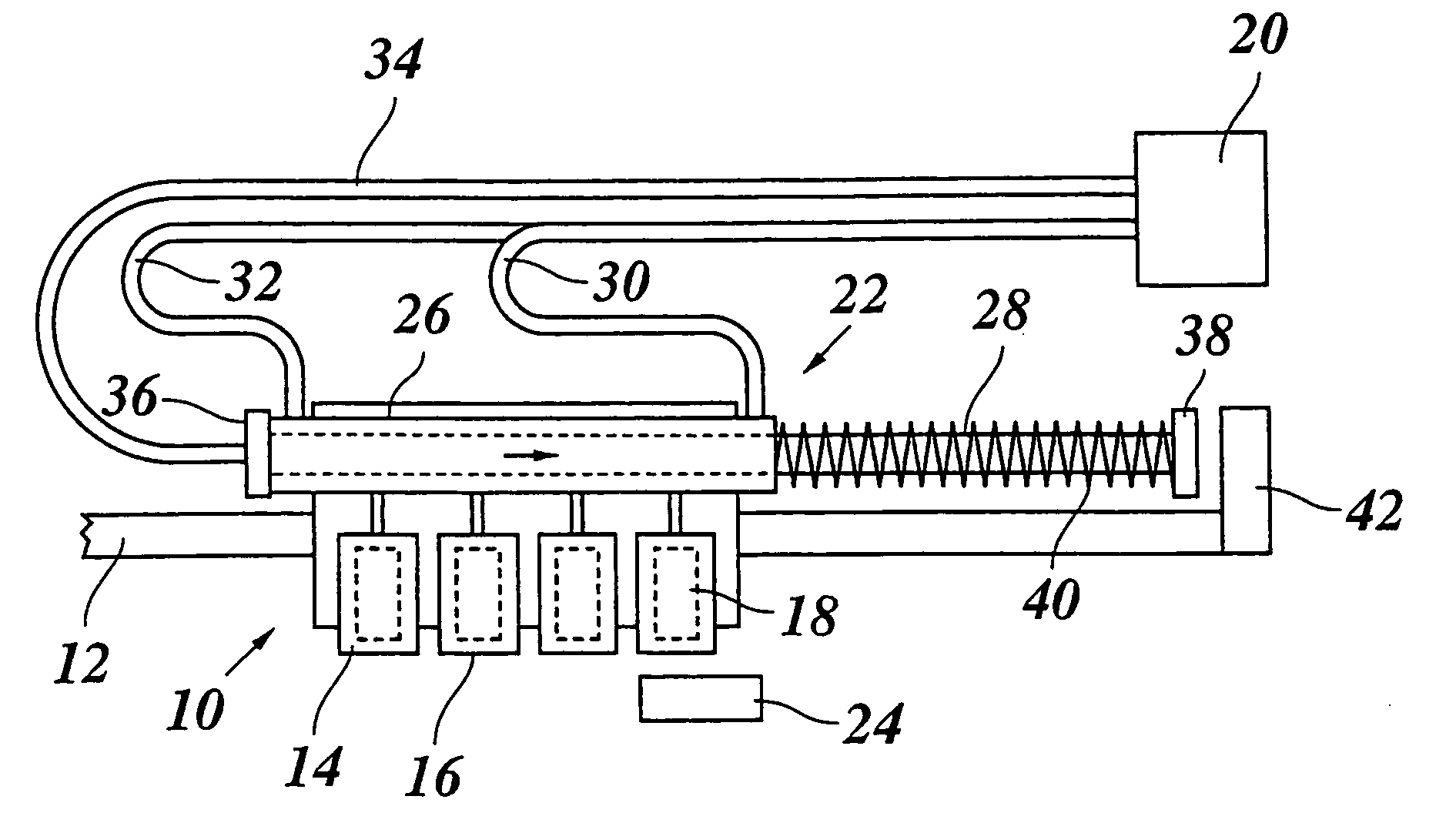
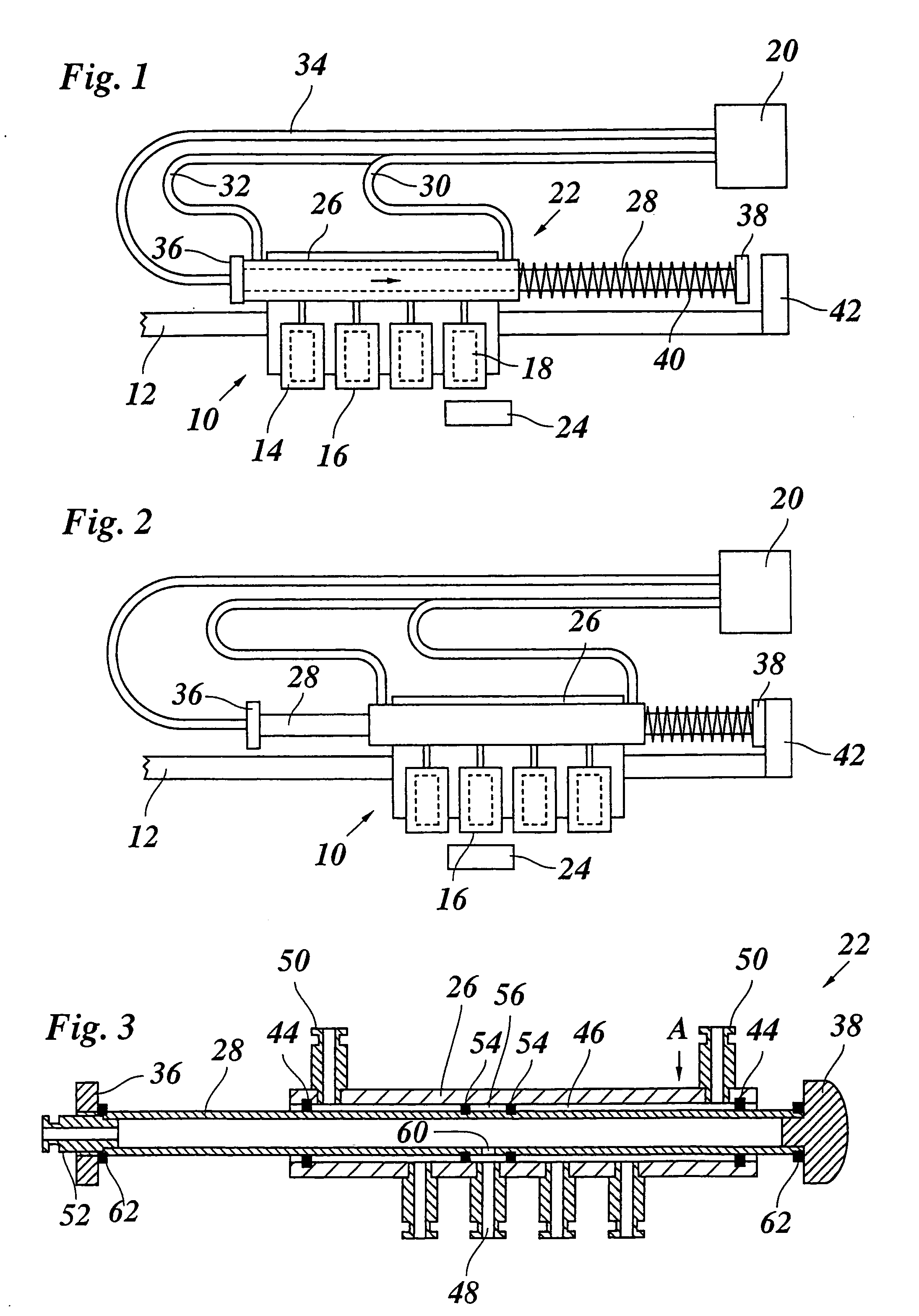
[0022] As is shown in FIG. 1, an ink jet printer to which the present invention is applicable includes a carriage 10 that is movable, for example, linearly along a guide rail 12 so as to scan a sheet of recording paper. The drawing shows only an end portion of the guide rail 12 outside of the area of the recording paper, so that the recording paper is not visible.

[0023] A number of printheads 14, four in this example, are mounted side by side on the carriage 10 and have nozzle faces 16 arranged in a common plane and facing downward in the drawing so as to oppose the recording paper when the carriage 10 scans the paper. Each printhead 14 further has an ink reservoir 18, and the ink reservoirs of the different printheads 14 contain liquid inks of different colors.

[0024] The part of the printer that has been shown in FIG. 1 accommodates a cleaning device for cleaning the nozzles in the nozzle faces 16 of the printheads 14 by flushing the nozzles with liquid ink from the ink container...


PUM


Abstract

A nozzle cleaning device for an ink jet printer containing a plurality of ink reservoirs, the cleaning device including a pressure source and a valve mechanism for selectively coupling the pressure source to the ink reservoirs, wherein the valve mechanism comprises a valve housing, and a piston movable within the valve housing and defining therewith a first pressure chamber and a second pressure chamber, said first and second pressure chamber being connected to the pressure source such that during idle conditions, the pressure source is in communication with the ink reservoirs through said first pressure chamber, and during cleaning conditions and through the movement of the piston, the pressure source is in selective communication with individual ink reservoirs through said second pressure chamber.

Description

[0001] This non-provisional application claims priority under 35 U.S.C. § 119(a) on Patent Application No. 04075043.2 filed in The European Patent Office on Jan. 14, 2004, which is herein incorporated by reference. BACKGROUND OF THE INVENTION [0002] The present invention relates to a nozzle cleaning device for an ink jet printer having a plurality of ink reservoirs, the cleaning device including a pressure source and a valve mechanism for selectively coupling the pressure source to the ink reservoirs. [0003] An ink jet printer typically contains a plurality of printheads, e.g. at least one for each color in the case of a multi-color printer. Each printhead has an array of nozzles through which ink droplets can be jetted out onto a recording medium, and also ink reservoirs that are in communication with each of the nozzles of the nozzle array through respective ink channels. In or adjacent to each of the ink channels an actuator, e.g. a piezoelectric actuator is provided which may be...

Claims


Application Information

Patent Timeline
Patent Type & Authority Applications(United States)
IPC IPC(8): B41J2/165
CPCB41J2/1652
Inventor VAN GERVEN, ANTONIUS J.J.
Owner OCE TECH
Why Eureka
Try Eureka