Printer, Printer head, and method of producing the printer head

a printing head and printer head technology, applied in printing, inking apparatus, etc., can solve the problems of ink leakage from the partition of the ink chamber, difficult to bring the orifice plate, and difficult to dispose individual drive elements, so as to prevent ink leakage and simple structure

Inactive Publication Date: 2002-09-12
SONY CORP
View PDF0 Cites 11 Cited by
  • Summary
  • Abstract
  • Description
  • Claims
  • Application Information

AI Technical Summary

Benefits of technology

0022] To overcome such problems, the present invention is applied to the printer, the printer head, or the method of producing the printer head, and, by disposing a wiring pattern below a partition of an ink chamber, a thickness-direction stepped portion is prevented from being formed at at least the partition of the ink chamber.
0023] According to the structure of the present invention, by preventing a thickness-direction stepped portion from being formed at at least the partition of the ink chamber by disposing a wiring pattern below the partition of the ink chamber, it is possible to, by using a simple structure, prevent formation of a gap between a material forming the partition of the ink chamber and a plate-shaped material, which is an orifice plate, disposed above the material forming the partition of the ink chamber. This makes it possible to prevent ink leakage, so that the orifice plate can be bonded by bringing it sufficiently into close contact with what it is to be bonded to.

Problems solved by technology

It is extremely difficult to dispose individual drive elements at the heating elements 8 disposed very close to each other.
However, the printer head 1 having such a structure has a problem in that it is difficult to bring the orifice plate 14 sufficiently into close contact with the dry film 13 and to bond it thereto.
The gap may cause ink to leak from the partition of the ink chamber.

Method used


Image

  • Printer, Printer head, and method of producing the printer head
  • Printer, Printer head, and method of producing the printer head
  • Printer, Printer head, and method of producing the printer head

Examples


first embodiment

[0034] (1) Structure of the First Embodiment

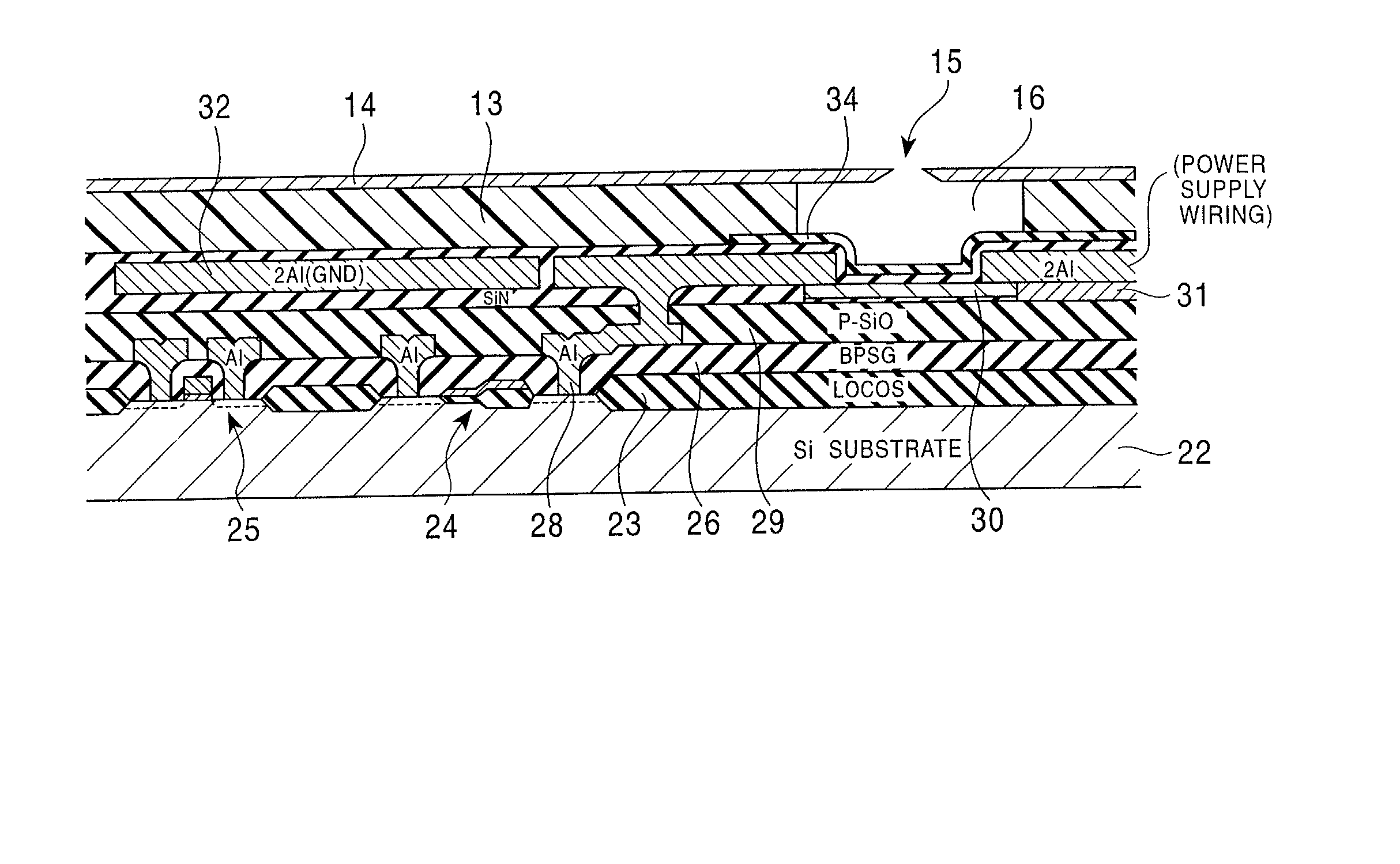
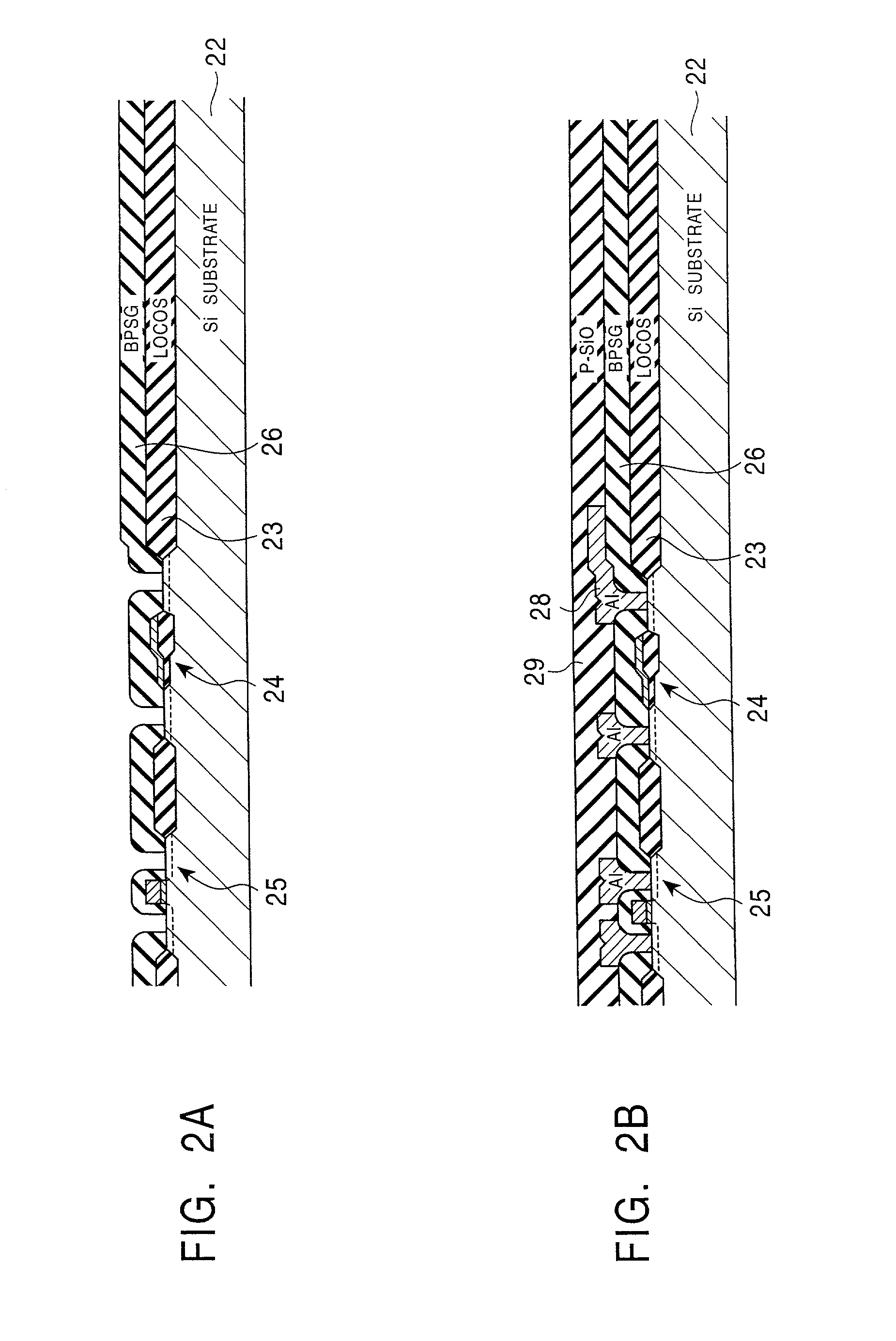
[0035] FIGS. 2A to 4 are sectional views illustrating the steps of producing a printer head of an embodiment of the present invention. In the production process, as shown in FIG. 2A, after washing a P-type silicon substrate 22, silicon nitride films are deposited thereon. In the process, by lithography and reactive on etching, the silicon substrate 22 is processed in order to remove the silicon nitride films deposited on areas other than predetermined areas where transistors are formed. By these operations, in the production process, silicon nitride films are formed in the areas on the silicon substrate 22 where the transistors are to be formed.

[0036] Then, in the production process, by a thermal oxidation operation, thermal silicon oxide films are formed in the areas from which the silicon nitride films have been removed, and, by the thermal silicon oxide films, an isolation area (LOCOS) 23 for isolating the transistors is formed. Thereaf...

second embodiment

[0052] (2) Second Embodiment

[0053] FIG. 5 is a plan view of the structures of second-layer wiring patterns and heating elements in a second embodiment of a printer head of the present invention, shown in contrast to those shown in FIG. 1. In the printer head of the embodiment, the second-layer wiring patterns and the heating elements are formed by the layout shown in FIG. 5 instead of the above-described layout shown in FIG. 1.

[0054] More specifically, with regard to each heating element 40, ends of two resistance patterns that extend substantially parallel to each other are connected by a corresponding second-layer wiring pattern 42A, so that a folded-back shape is formed. Then, both ends of each of the heating elements 40 having folded-up shapes are connected to the power supply line and the switching transistor, respectively, by corresponding second-layer wiring patterns 42B and 42C.

[0055] In the printer head, the wiring patterns 42B and the wiring patterns 42C are disposed suffi...

third embodiment

[0060] (3) Third Embodiment

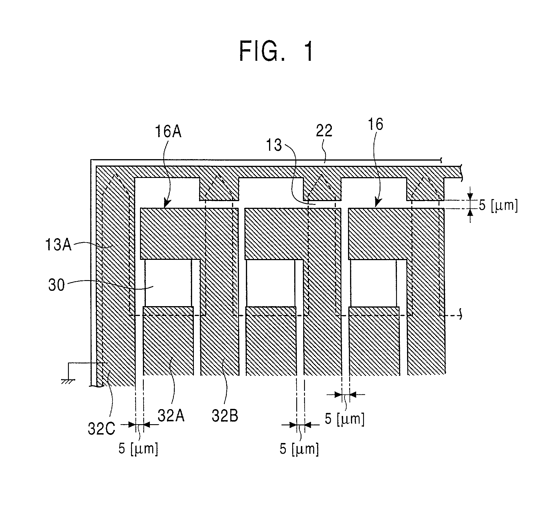
[0061] FIG. 6 is a plan view of the structures of second-layer wiring patterns and heating elements of a printer head of a third embodiment of the present invention, shown in contrast to those of FIG. 1. The printer head of the embodiment makes it possible to prevent leakage of liquid by preventing formation of a stepped portion as a result of extending wiring patterns 52A and 52B connected to heating elements 30.

[0062] More specifically, in the printer head, the wiring patterns 52B, which are connected to edge-side end portions of the corresponding heating elements 30, are formed so that edge-side portions thereof below ink chamber partitions protrude towards an edge side. This makes it possible to prevent formation of stepped portions between adjacent ink chambers, so that ink leakage can be prevented from occurring.

[0063] In contrast, with regard to the wiring pattern at the endmost side, a connecting portion thereof which connects to the corresponding ...


PUM


Abstract

The invention provides a printer, a printer head, and a method of producing the printer head. In particular, the invention is applied to a printer which makes use of a process in which ink drops are caused to flow out by heating using a heater, so that an orifice plate can be bonded by sufficiently bringing it into close contact with what it is to be bonded to. In the invention, by disposing first, second, and third wiring patterns below partitions of corresponding ink chambers, thickness-direction stepped portions are prevented from being formed at at least the partitions of the corresponding ink chambers.

Description

BACKGROUND OF THE INVENTION[0001] 1. Field of the Invention[0002] The present invention relates to a printer, a printer head, and a method of producing the printer head. In particular, the present invention is applicable to a printer which makes use of a process which causes ink droplets to fly out as a result of heating by a heater. The present invention makes it possible to, by preventing a thickness-direction stepped portion from being formed at at least a partition of an ink chamber as a result of disposing a wiring pattern below the partition of the ink chamber, bring an orifice plate sufficiently into close contact with what it is to be bonded to and bond it thereto.[0003] 2. Description of the Related Art[0004] In recent years, in the field of image processing and the like, there has been an increasing need for color hard copies. To respond to this need, there has been conventionally proposed a sublimation thermal transfer process, a fusion thermal transfer process, an inkjet...

Claims


Application Information

Patent Timeline
Patent Type & Authority Applications(United States)
IPC IPC(8): B41J2/05B41J2/14B41J2/16
CPCB41J2/14072B41J2/14129B41J2/1603B41J2/1623B41J2/1628B41J2/1631B41J2/1642B41J2/1646B41J2202/13
Inventor MIYAMOTO, TAKAAKIKOHNO, MINORUTANIKAWA, TORU
Owner SONY CORP
Why Eureka
Try Eureka