
Storage device for storing and/or transporting nuclear fuel assemblies

a storage device and nuclear fuel technology, applied in nuclear elements, nuclear engineering problems, greenhouse gas reduction, etc., can solve the problems of providing a substantial limitation of constraints and deformations of latter in lateral, and achieve the reduction of constraints and deformations, the increase of cross-over zone stiffness, and the effect of enhancing mechanical rigidity of storage devices

Active Publication Date: 2011-06-14
TN INT (FR)
View PDF10 Cites 4 Cited by
  • Summary
  • Abstract
  • Description
  • Claims
  • Application Information

AI Technical Summary

Benefits of technology

The invention proposes a storage device for nuclear fuel assemblies that solves the problems of previous designs. The device includes a plurality of adjacent housings, each with lateral walls that can receive a nuclear fuel assembly. The lateral walls are made of a first material, such as aluminium, and a second material, such as steel or titanium, which is stronger than the first material. The tubular cross-section elements in the structural assemblies are made of stainless steel or titanium alloy, which offer better mechanical resistance. The design of the storage device is simple and cost-effective. The mechanical joints between the tubular cross-section elements are reinforced, and the device satisfies all four essential functions. The design also provides optimal shielding against gamma rays and neutrons.

Problems solved by technology

This can be explained in particular by the fact that these tubular cross-section elements, made from steel, titanium or one of the alloys thereof, have a high bending inertia module for a given linear density, providing a substantial limitation of the constraints and deformations of the latter in lateral free-fall as well as in vertical free-fall.

Method used


Image

  • Storage device for storing and/or transporting nuclear fuel assemblies
  • Storage device for storing and/or transporting nuclear fuel assemblies
  • Storage device for storing and/or transporting nuclear fuel assemblies

Examples


Embodiment Construction

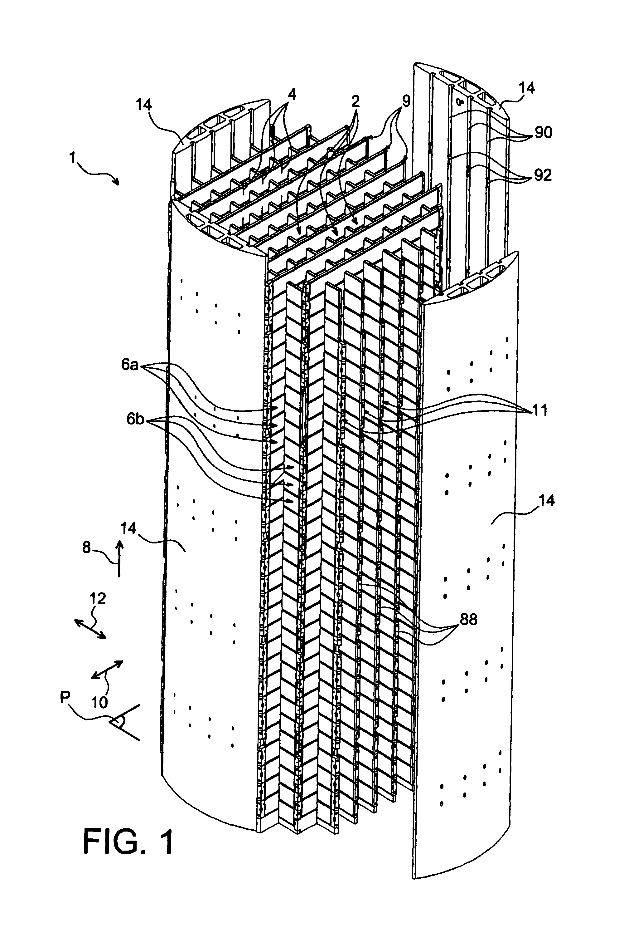
[0061]In reference to FIG. 1, a storage device 1 is shown provided to be placed in a casing (not shown in this figure) intended for the transporting and / or storing of nuclear fuel assemblies (not shown), more preferably irradiated.

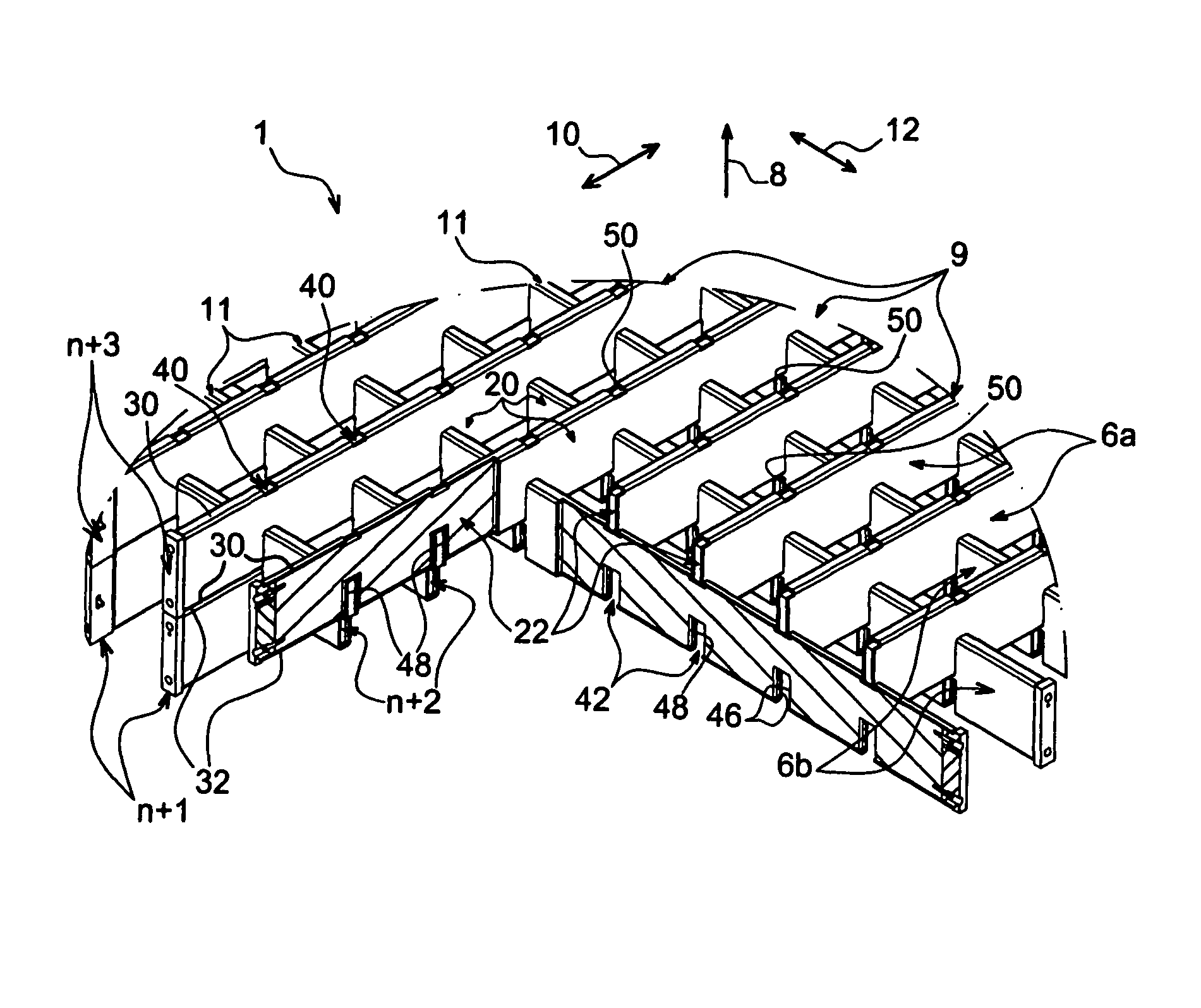
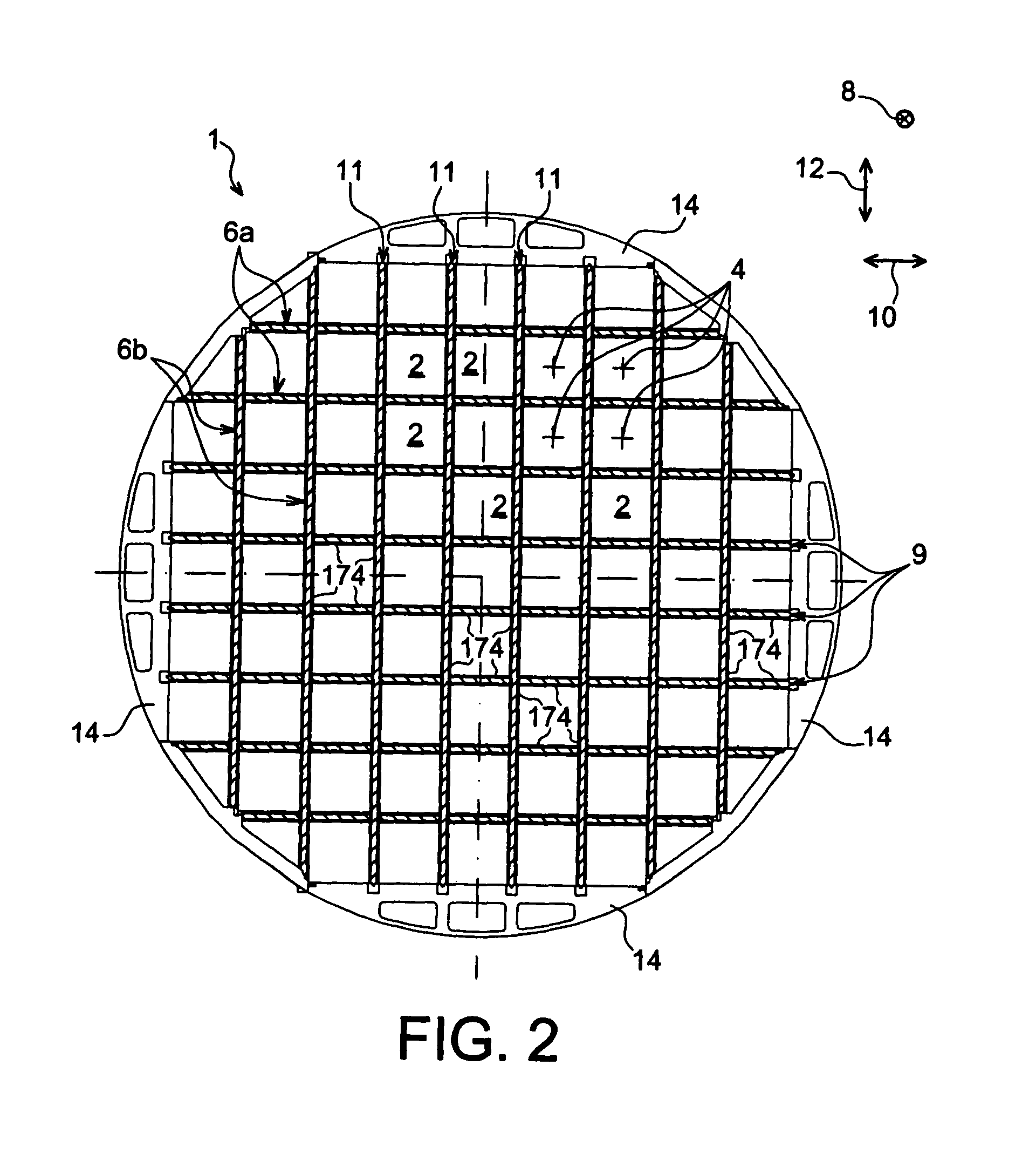
[0062]As can be seen in FIG. 1, storage device 1 includes a plurality of adjacent housings 2 disposed in parallel, with the latter extending each along a longitudinal axis 4. Housings 2 are each able to receive at least one fuel assembly of square cross-section, and more preferably a single one.

[0063]Housings 2 are therefore provided in such a way that they are juxtaposed one in relation to the others. They are realised by the intermediary of a plurality of slotted structural assemblies 6a, 6b, these assemblies 6a, 6b being stacked according to a stacking direction that is parallel to the longitudinal axes 4 of housings 2, as shown schematically by arrow 8 in FIG. 1. More precisely, stacking direction 8 extends from the bottom of a storage device towards a...


PUM


Abstract

The invention relates to a storage device (1) for the storing and / or transporting of nuclear fuel assemblies, including a plurality of adjacent housings each having a lateral wall and being able to receive a nuclear fuel assembly, the lateral walls being realized at least in part using stacking and intercrossing slotted structural assemblies (6a, 6b), each structural assembly including at least one plate (22) realized in a first material comprising aluminum. According to the invention, each structural assembly (6a, 6b) further includes a tubular cross-section element (20) inside of which is located said at least one plate (22), this tubular cross-section element (20) being realized in a second material selected from steels and titanium and alloys thereof.

Description

CROSS REFERENCE TO RELATED APPLICATIONS OR PRIORITY CLAIM[0001]This application claims priority to French Patent Application No. 06 55110, filed Nov. 27, 2006.TECHNICAL FIELD[0002]This invention generally relates to a storage device for storing and / or transporting nuclear fuel assemblies. More particularly but not exclusively, the invention relates to a storage device for the transporting and storing of irradiated nuclear fuel assemblies. This type of device, normally subjected to high temperatures, can require, in cases where the temperatures are the highest, steel elements in order to ensure mechanical resistance that is satisfactory overall.[0003]The invention further relates to a container including a casing wherein is disposed such a storage device for storing and / or transporting nuclear fuel assemblies.PRIOR ART[0004]Traditionally, such devices also called storage “baskets” or “plate racks”, are of a substantially circular cylindrical cross-section form, and have a plurality o...

Claims


Application Information

Patent Timeline
Patent Type & Authority Patents(United States)
IPC IPC(8): G21C19/00G21F5/00
CPCG21C19/07G21F5/012G21Y2004/30G21Y2002/303G21Y2002/304G21Y2002/207Y02E30/30
Inventor ANDRE, REGISFOUSSARD, GUILLAUME
Owner TN INT (FR)
Learn More