Dual path kiln

a dual-path kiln and kiln technology, applied in the direction of drying machines with progressive movements, other chemical processes, furnaces, etc., can solve the problems of requiring a significant amount of time and energy, and too quickly drying can have adverse effects on lumber

Active Publication Date: 2011-06-21
POLLARD LEVI A
View PDF390 Cites 53 Cited by
  • Summary
  • Abstract
  • Description
  • Claims
  • Application Information

AI Technical Summary

Problems solved by technology

This opens the chamber to atmospheric conditions and can often require a significant amount of time and energy to bring the next charge of green lumber up to drying conditions.
While lumber is typically dried as fast as possible depending on the cell structure, drying too rapidly can have adverse affects on the lumber, such as checking, splitting, warping, cupping, and the like.

Method used


Image

  • Dual path kiln
  • Dual path kiln
  • Dual path kiln

Examples


Embodiment Construction

[0012]In the following detailed description, reference may be made to the accompanying drawings which form a part hereof, and in which is shown by way of illustration embodiments in which the invention may be practiced. It is to be understood that other embodiments may be utilized and structural or logical changes may be made without departing from the scope of the present invention. Therefore, the following detailed description is not to be taken in a limiting sense, and the scope of embodiments in accordance with the present invention is defined by the appended claims and their equivalents.

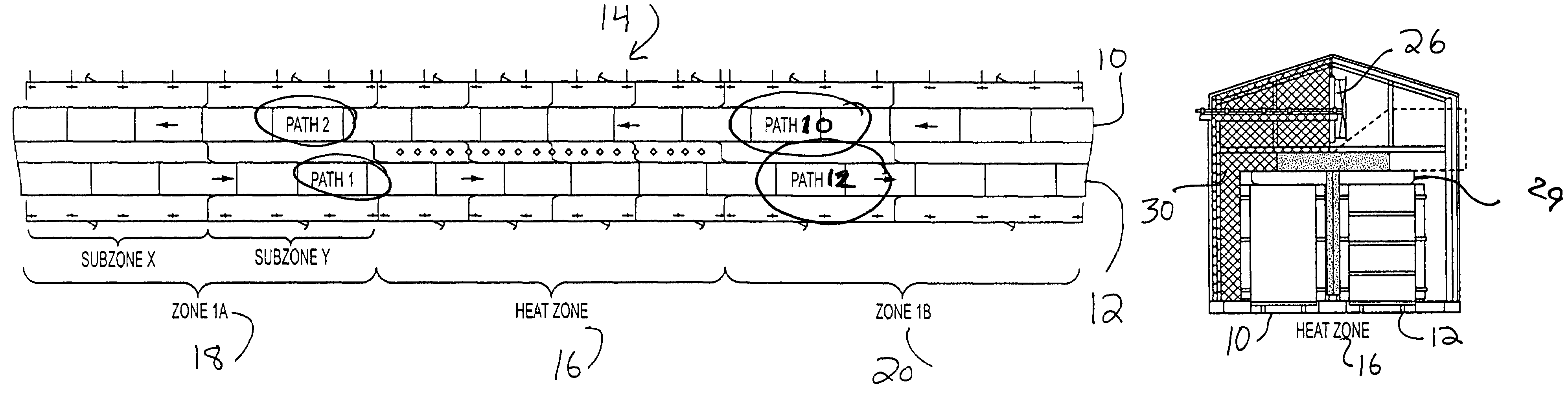
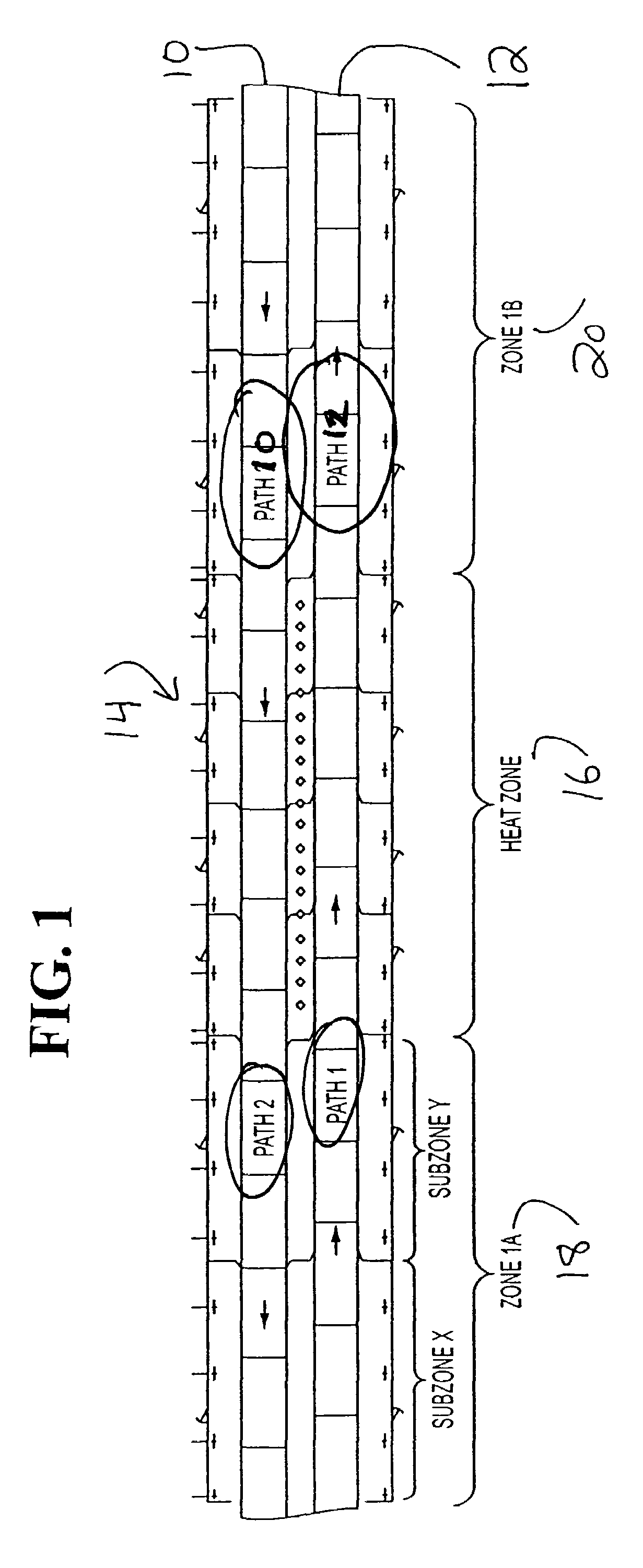
[0013]Embodiments of the present invention are directed to a continuous type lumber drying process, where, in FIG. 1, at least two different opposing paths 10 and 12 move green lumber through a kiln 14 such that a dried lumber charge exits a first end of the kiln while a green lumber charge enters the first end. Embodiments allow for the heat dissipating from the dried lumber after exiting a dry...


PUM


Abstract

An dual path kiln is provided that includes a kiln having one or more chambers and at least two lumber charge paths adapted to convey lumber through the kiln in opposite directions.

Description

CROSS-REFERENCE TO RELATED APPLICATIONS[0001]This application is a Continuation-In-Part of U.S. patent application Ser. No. 11 / 414,262, filed 1 May 2006 and now abandoned, which claims priority to U.S. Provisional Patent Application No. 60 / 683,859, filed 23 May 2005.FIELD OF THE INVENTIONBACKGROUND TO THE INVENTION[0002]Embodiments of the present invention relate to the field of kilns used in the drying of lumber, and more particularly pertains to an improved kiln having a continuous opposing feed and discharge stream at each end of the kiln where the passing of the dried lumber preheats the green lumber.BACKGROUND[0003]Drying lumber is typically performed in a batch kiln process, where an insulated chamber is used that is adapted to control several drying process conditions, including, but not limited to air temperature in the kiln, air speed across the lumber, and the relative humidity in the chamber. As these kilns are a closed atmosphere, packages of sawn lumber, often referred ...

Claims


Application Information

Patent Timeline
Patent Type & Authority Patents(United States)
IPC IPC(8): F26B11/00
CPCF26B15/12F26B21/02F26B2210/16
Inventor POLLARD, LEVI A.
Owner POLLARD LEVI A
Why Eureka
Try Eureka