Double latched scaffold connector

a scaffold connector and double-latched technology, applied in the direction of securing devices, constructions, building aids, etc., can solve the problems of high torsional force, weak connection, and possible failure of connectors, and achieve the effect of quick and efficient installation or disassembly

Active Publication Date: 2011-07-05
EXCEL MODULAR SCAFFOLD & LEASING
View PDF26 Cites 24 Cited by
  • Summary
  • Abstract
  • Description
  • Claims
  • Application Information

AI Technical Summary

Benefits of technology

[0007]Therefore, it is an object of this invention to provide an improved scaffold latch mechanism that latches at tw

Problems solved by technology

However, because the bottom hook of the '532 connector and '307 connector is not latched to the bottom ring member, the connector is still weak when subject to high torsional forces; for instance, it is not rec

Method used


Image

  • Double latched scaffold connector
  • Double latched scaffold connector
  • Double latched scaffold connector

Examples


Embodiment Construction

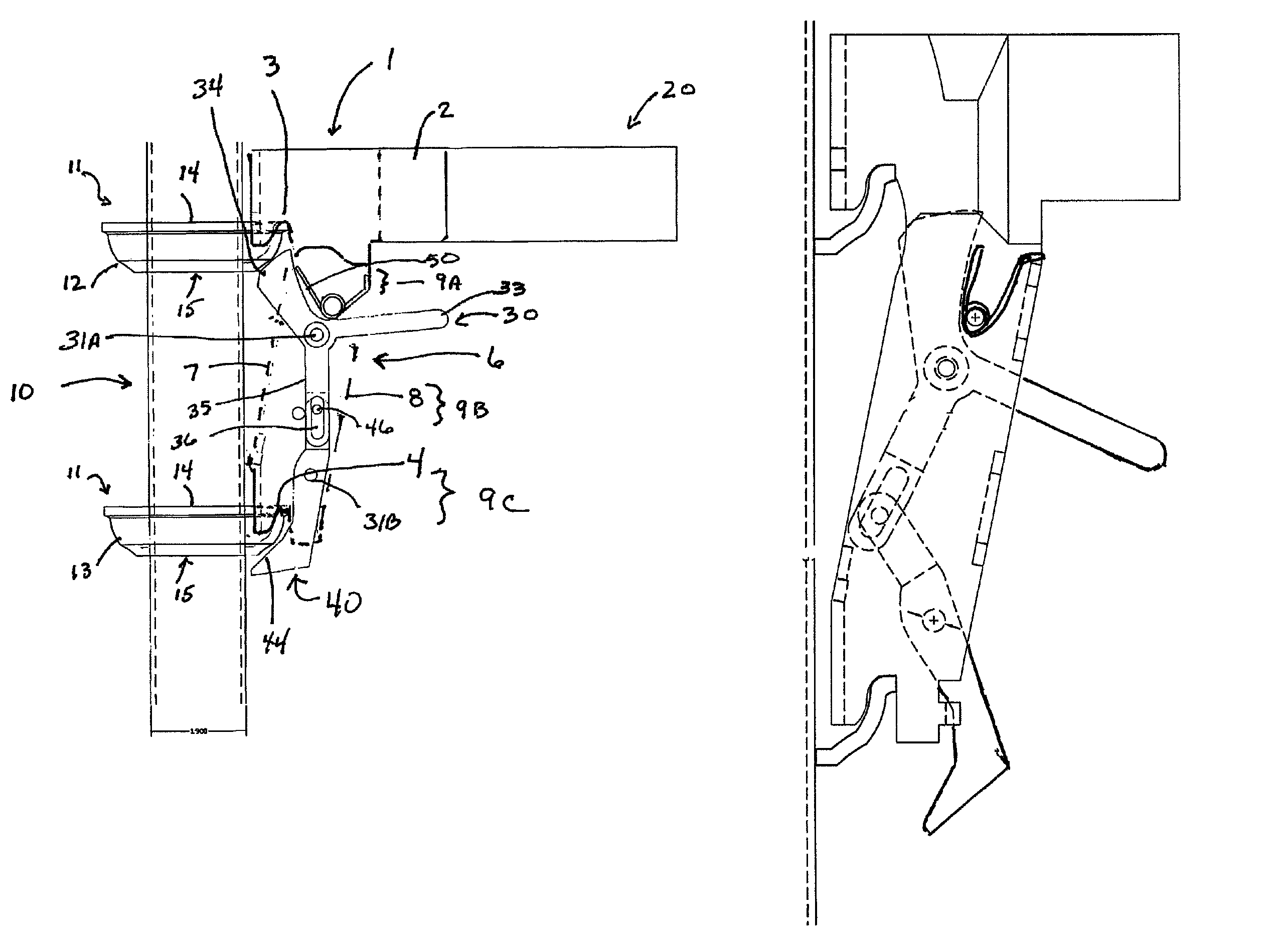
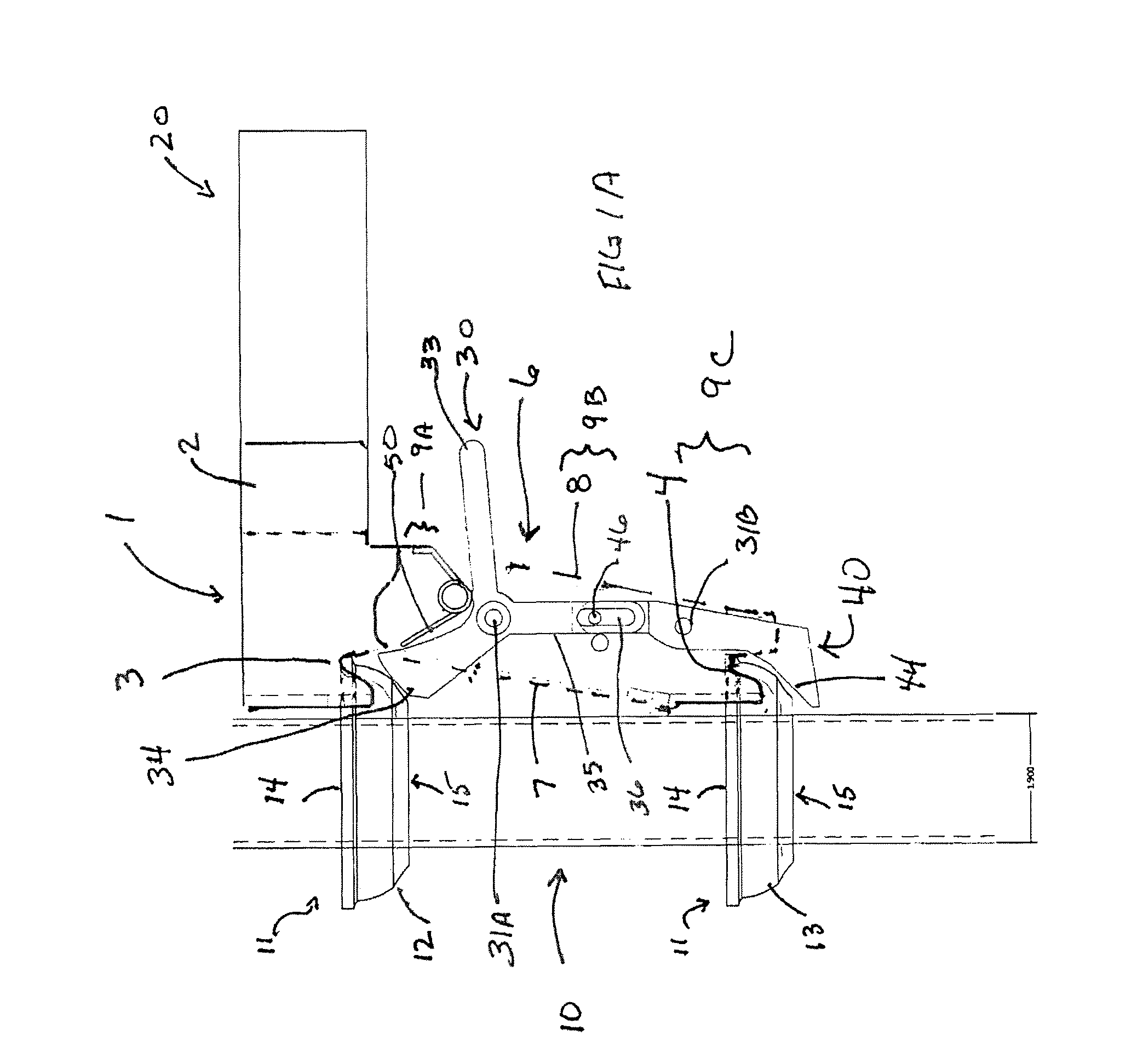
[0012]Shown in FIG. 1A is a scaffold connector 1, joining a vertical scaffold member 10 with a horizontal scaffold member 20. Positioned on the vertical scaffold member 10 is a plurality of ring members 11. In general, the vertical scaffold member 10 will have a series of ring members 11 positioned at regular intervals along the length of the vertical member. Ring members 11 are positioned in a vertically spaced apart relationship on the vertical scaffold member 10. Shown in FIG. 1A are upper ring member 12, and lower ring member 13. Ring members have an upper side 14 and a lower side 15. As shown, ring members 11 are upwardly curved cup shaped members. Alternative ring members can be seen in U.S. Pat. Nos. 4,044,523 and 4,039,264 hereby incorporated by reverence

[0013]The connector 1 is fixedly attached to the horizontal scaffold member 20, preferably by welding. As shown, connector 1 has a connector body with a top housing 2 shaped to accept a horizontal scaffold member 20. Protrud...


PUM


Abstract

An improved scaffold connection is provided, attachable to a vertical scaffold member having a plurality of ring members. The scaffold joint has an upper side and a lower side, and an upper hook section and a lower hook section engagable with the ring members on the vertical scaffold members. The invention includes two latches to lock the joint to two ring members, where the two latches are mechanically connected.

Description

BACKGROUND OF THE INVENTION[0001]1. Field of the Invention[0002]This invention relates generally to connections for scaffolding and, more particularly, to latchable scaffolding connections between horizontal and vertical scaffold members.[0003]2. Background of the Invention[0004]Many different designs have been employed to secure the ends of horizontal scaffold members to vertical scaffold members. Because of a concern for a positive locking arrangement, prior art connections employ a latch assembly, whereby the connection between a horizontal and a vertical member is held in place against an uplifting force by some type of latch. One such joint is disclosed in U.S. Pat. No. 4,445,307, which discloses a connector positioned on a horizontal scaffold member, where the connector has two vertically spaced hook sections. These hook sections couple with two vertically spaced upstanding ring members located on the vertical scaffold member. To withstand an uplifting force, the connector inc...

Claims


Application Information

Patent Timeline
IPC IPC(8): E04G7/00
CPCE04G7/306E04G7/307Y10T403/30
Inventor HAYMAN, YATES W.
Owner EXCEL MODULAR SCAFFOLD & LEASING
Why Eureka
Try Eureka