
Mobility device for amputee and leg-injured persons

a technology for amputees and people with leg, ankle, foot injuries, applied in the direction of wheelchairs/patient conveyances, bicycles, trailer steering, etc., can solve the problems of inability to adjust, increase etc., to achieve the effect of reducing the cost of mobility devices

Active Publication Date: 2011-07-19
BENNETT BECKY J
View PDF100 Cites 13 Cited by
  • Summary
  • Abstract
  • Description
  • Claims
  • Application Information

AI Technical Summary

Problems solved by technology

Many mobility devices intended for use by amputees are undesirably cumbersome, expensive, and / or surprisingly semi-unstable, especially when used by heavier persons.
Further, the devices often have limited (or zero) adjustability, limited (or zero) foldability, and limited (or zero) storage capacity for transporting items along with the amputee.
Further, their width is often so great that it is difficult (or not possible) for them to be manipulated around corners, and through door-openings and narrow spaces often found in homes and buildings.
Also, many such devices have poor cornering capability, leading to difficulty especially for a novice user.
This can create a serious risk of falling due to the instability created when the shifting weight of a large adult user is borne by the wheeled device at waist level, even if the wheels are made to lock or move to a recessed position when bearing weight.
Other mobility devices are collapsible in some fashion, but the act of collapsing and / or expanding them requires significant effort and / or help from a third party helper.
Some mobility devices have a storage bag or basket, however there is often limited room on the cart and also nothing to prevent the stored items from tipping and / or mixing.
Another problem is that existing mobility devices are not adjustable to accommodate people with different body shapes and preferences.
Still further, most cannot be adjusted for use by children, but instead require that a separate smaller version of the device be purchased.
Another problem is that known mobility devices have an unattractive appearance.
However, when removed, it is difficult for the amputee to get around.
Concurrently, it is cumbersome to reattach the prosthesis.
This can lead to falls and injury.

Method used


Image

  • Mobility device for amputee and leg-injured persons
  • Mobility device for amputee and leg-injured persons
  • Mobility device for amputee and leg-injured persons

Examples


Embodiment Construction

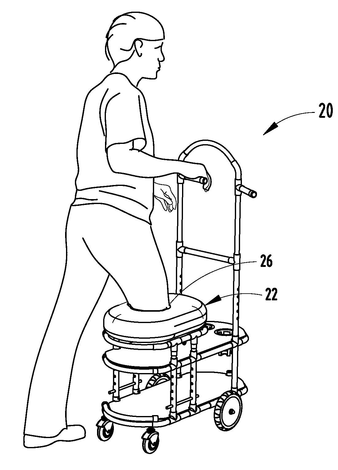
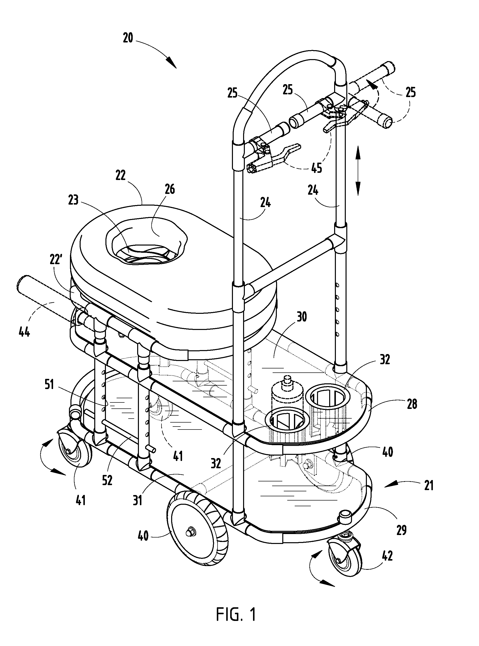
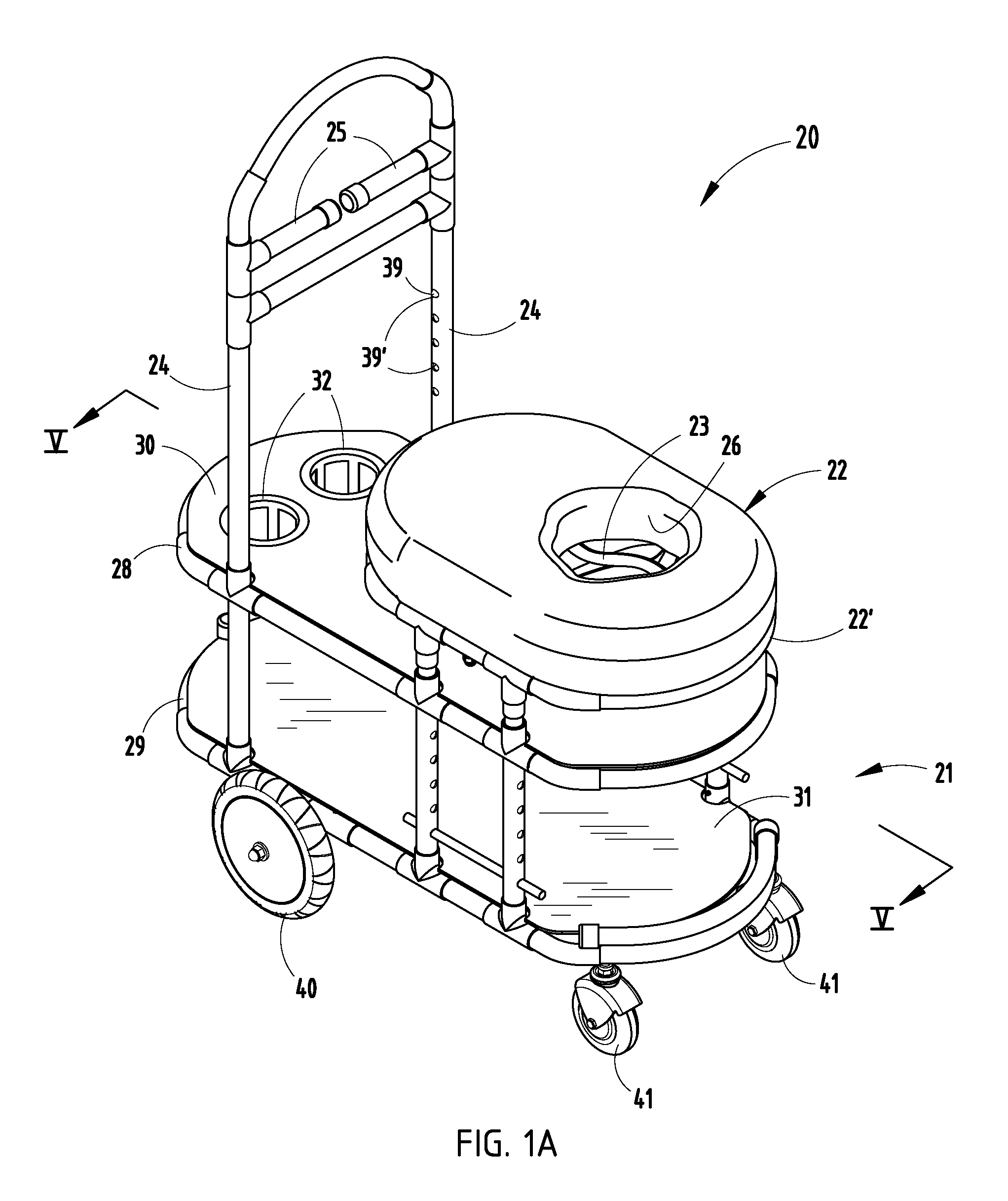
[0034]An amputee mobility device 20 (FIG. 1) includes a wheeled frame 21 (FIGS. 1-2), and apertured seat 22 (also called “cushioned structural member” and “horizontal structural support member”) with a pocket 23 (also called “basket”) suitable for directly receiving the stump (i.e., amputated leg) of an amputee, such that an amputee can simply place their stump in position and move with stability across a floor. The basket 23 can be custom-made for an individual, such as by molding or sewn fabric, or can be made adjustable such as by using hook-and-loop material (i.e., Velcro®). The present device is particularly useful since, for example, amputees prefer not to struggle to attach a prosthesis when their goal is simply to move a short distance. On the other hand, it is potentially quite unsafe for an amputee with one leg to hop across a room, whether they use an assistance device or not.

[0035]The illustrated frame 21 includes upper and lower loop-shaped subframes 28 and 29 supported...


PUM


Abstract

An amputee mobility device includes a wheeled frame, and seat with webbed pocket for receiving an amputated leg. The seat is adjustable height adjustable, as is the pocket for customizing to individuals. Adjustable handles allow amputees to move themselves, or allow a helper to push like a wheelchair. In one form, the frame includes front and rear articulated subframes. In another form, the wheeled frame forms an elongated rigid frame, with two fixed-axle wheels and two rear-located steerable wheels and one front-located steerable wheel. In another form, the frame includes two fixed-axle wheels and two steerable wheels arranged to function somewhat like a wheeled walking cane. Optional features include outriggers for leg protection, a foldable frame for compact storage and shipment, bicycle-like lockable hand brakes, a seat without aperture for supporting a lower leg extending horizontally, storage shelves, and cup holders.

Description

[0001]This application claims benefit under 35 U.S.C. §119(e) of provisional application Ser. No. 61 / 079,193, filed Jul. 9, 2008, entitled MOBILITY DEVICE FOR AMPUTEE AND LEG-INJURED PERSONS, the entire contents of which are incorporated herein in their entirety.BACKGROUND[0002]The present invention relates to mobility devices for amputees or individuals with leg, ankle, or foot injuries, and more particularly relates to a wheeled device with an adjustable seat adapted to engage and support an amputated limb of a person, and / or adapted for use as a wheelchair, and / or adapted for use as a walker, and / or adapted for transport of items (such as personal items of the amputee).[0003]Many mobility devices intended for use by amputees are undesirably cumbersome, expensive, and / or surprisingly semi-unstable, especially when used by heavier persons. Further, the devices often have limited (or zero) adjustability, limited (or zero) foldability, and limited (or zero) storage capacity for trans...

Claims


Application Information

Patent Timeline
Patent Type & Authority Patents(United States)
IPC IPC(8): B62M1/12
CPCA61G5/00A61H3/04A61G2005/085A61G2005/0883A61G2005/0891A61G2005/1091A61G2005/127A61H2003/005A61H2003/046A61H2201/0161A61H2201/1633A61G5/085A61G5/0883A61G5/0891A61G5/1091A61G5/127
Inventor BENNETT, BECKY J.
Owner BENNETT BECKY J
Learn More