Apparatus, method and computer program product for determining respiratory condition

a technology of respiratory condition and apparatus, applied in the field of apparatus, a method and a computer program product for determining respiratory condition, can solve problems such as improper pillow height, road accidents, and people experiencing hypoxic condition

Inactive Publication Date: 2011-07-19
TDK CORPARATION
View PDF15 Cites 9 Cited by
  • Summary
  • Abstract
  • Description
  • Claims
  • Application Information

AI Technical Summary

Problems solved by technology

In recent years, drivers' falling asleep while driving a moving vehicle, such as a rail, a car or the like, has resulted in road accidents.
Further, people may experience hypoxic condition, but not apnea, which may result from improper pillow height.
In addition, a chair-type child seat or a stroller causes hypoxia to children.
Therefore, it is difficult to make measurement when airway occlusion, bruxism, or the like occurs, which has a high frequency range, even though complete apnea does not occur.
In addition, it is not possible for the external microphone to make measurement, when snoring, bruxism or the like does not appear to the outside as sounds.
Therefore, it is difficult to detect a change in breath sounds due to the state of respiratory obstruction.

Method used


Image

  • Apparatus, method and computer program product for determining respiratory condition
  • Apparatus, method and computer program product for determining respiratory condition
  • Apparatus, method and computer program product for determining respiratory condition

Examples


first embodiment

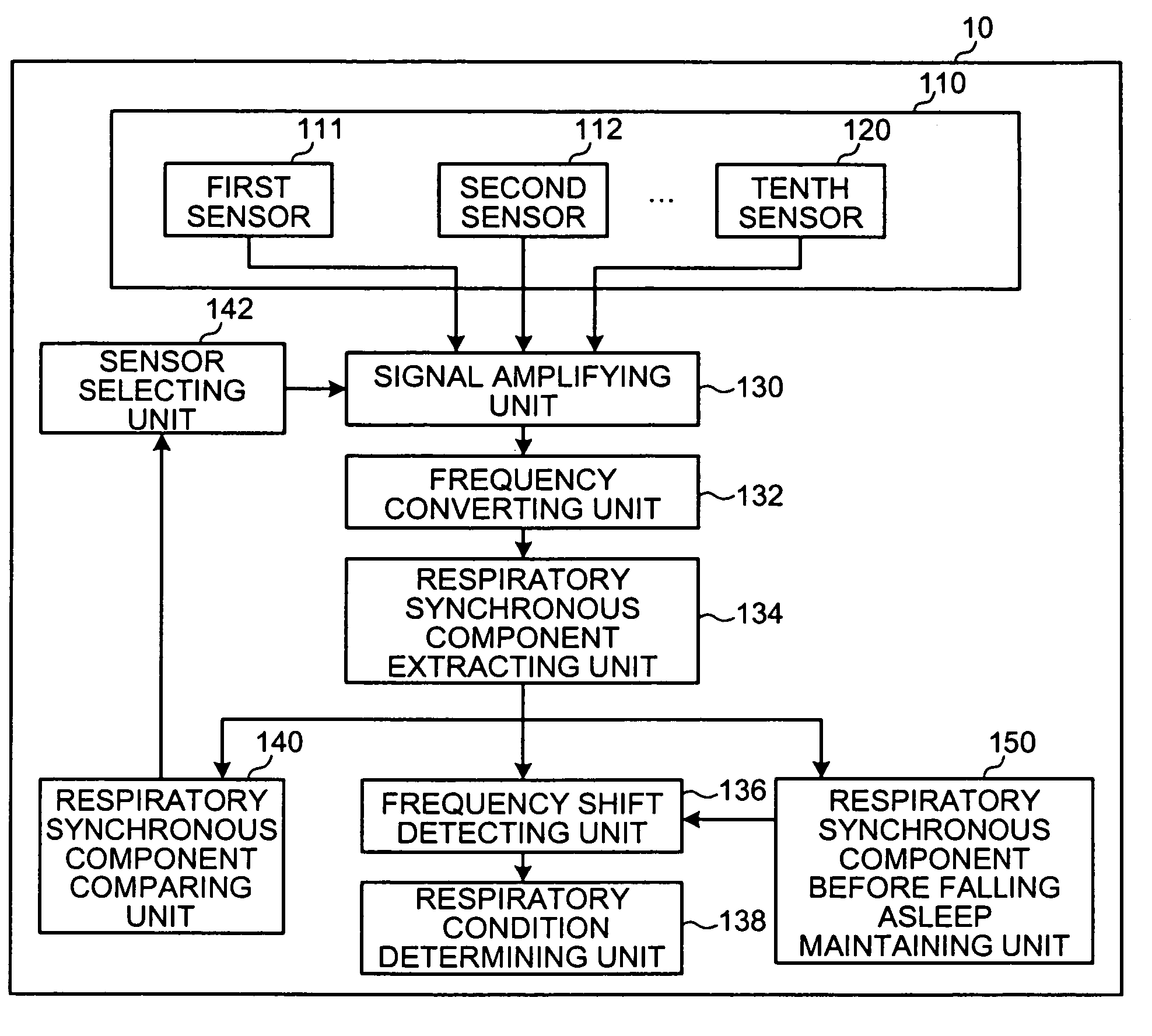
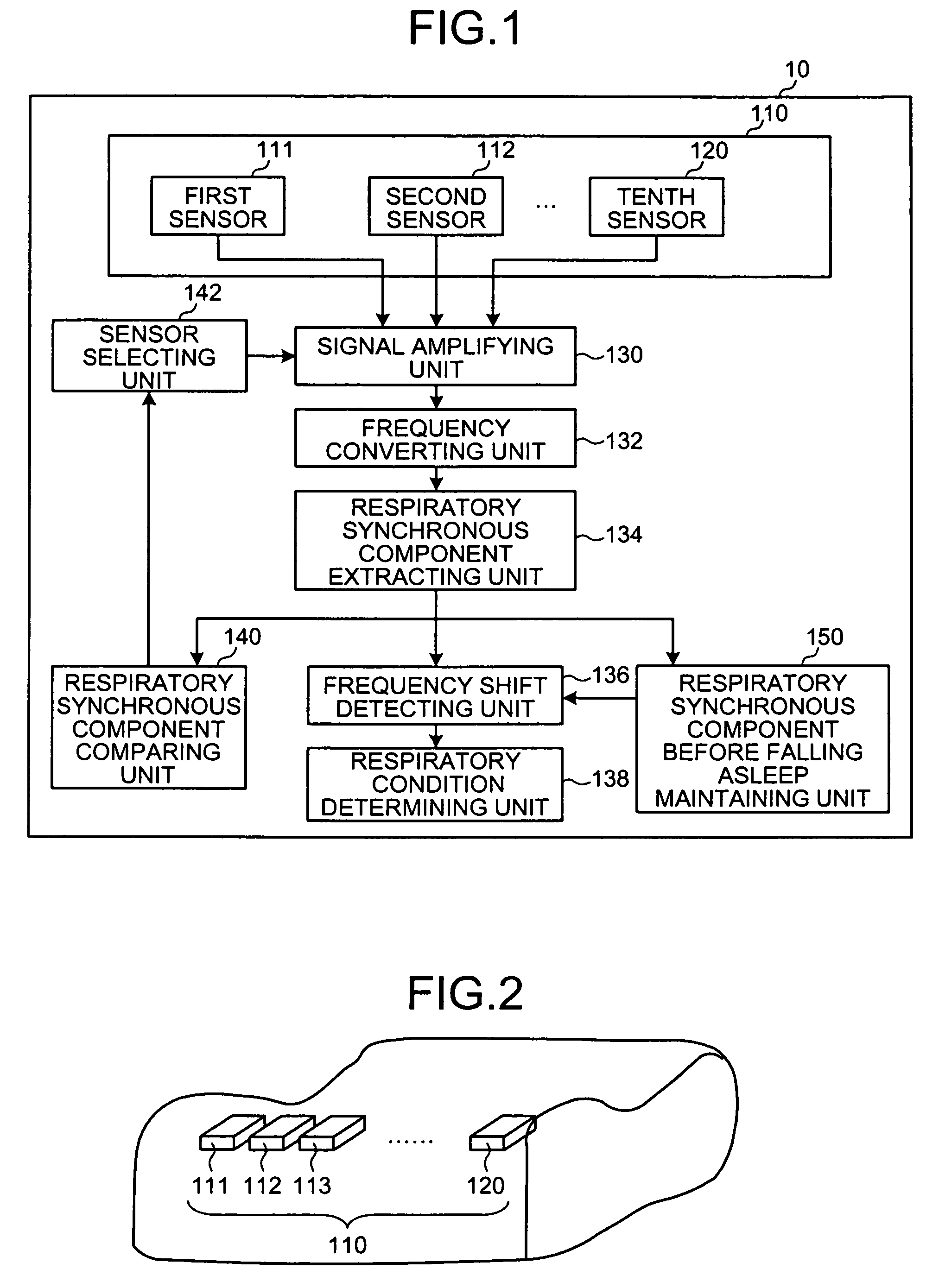
[0025]FIG. 1 is a block diagram illustrating an entire configuration of an apparatus for determining a respiratory condition 10 according to a first embodiment of the present invention. The apparatus for determining a respiratory condition 10 includes a sensor array 110 having a plurality of sensors 111 to 120 that detect breath sounds passing through a subject's airway while being in contact with the subject's skin, a signal amplifying unit 130, a frequency converting unit 132, a respiratory synchronous component extracting unit 134, a frequency shift detecting unit 136, a respiratory condition determining unit 138, a respiratory synchronous component comparing unit 140, a sensor selecting unit 142, and a respiratory synchronous component, before falling asleep, maintaining unit 150.

[0026]The signal amplifying unit 130 amplifies breath sound signals detected from the respective sensors 111 to 120. The frequency converting unit 132 performs frequency conversion, such as Fourier tran...

second embodiment

[0067]FIG. 9 is a diagram illustrating the external appearance of an apparatus for determining a respiratory condition 10 according to a second embodiment. A plurality of air bags 301 to 310 are provided under respective sensors 111 to 120. In this case, one air bag is provided so as to correspond to one sensor. The air bag according to the present embodiment corresponds to a pressing member described in the appended claims.

[0068]FIG. 10 is a block diagram illustrating a functional configuration of the apparatus for determining a respiratory condition 10 according to the second embodiment. The apparatus for determining a respiratory condition 10 according to the second embodiment further includes an air bag controlling unit 160, in addition to the functional configuration of the apparatus for determining a respiratory condition 10 according to the first embodiment. The air bag controlling unit 160 outputs to the air bag an instruction that the air bag, on which a sensor selected by ...

third embodiment

[0078]FIG. 11 is a block diagram illustrating a functional configuration of an apparatus for determining a respiratory condition 10 according to a third embodiment. The apparatus for determining a respiratory condition 10 according to the third embodiment does not include the respiratory synchronous component comparing unit 140 and the sensor selecting unit 142. In addition, only one sensor is provided. In this configuration, the apparatus for determining a respiratory condition 10 according to the third embodiment is different from the apparatus for determining a respiratory condition 10 according to the other embodiments.

[0079]The apparatus for determining a respiratory condition 10 according to the third embodiment may be mounted in a stethoscope or the like. A doctor or a subject searches for a portion suitable for measurement while checking by the stethoscope or the like, and thus detects a breath sound signal through the stethoscope in a state where the sensor is in contact wi...


PUM


Abstract

An apparatus for determining a respiratory condition includes a breath sound measuring unit 111 measuring a breath sound passing through a subject's airway by a breathing; a frequency converting unit 132 converting a frequency on the breath sound to obtain a frequency spectrum; a respiratory synchronous component extracting unit 134 extracting a respiratory synchronous component, which varies depending on the breathing, from the frequency spectrum; a frequency distribution detecting unit 136 detecting a frequency distribution of the respiratory synchronous component; and a respiratory condition determining unit 138 determining a subject's respiratory condition based on the frequency distribution. According to the apparatus, various symptoms, such as airway occlusion, respiratory obstruction and the like in relation to breathing during sleep can be determined.

Description

CROSS-REFERENCE TO RELATED APPLICATIONS[0001]This application is based upon and claims the benefit of priority from the prior Japanese Patent Application No. 2005-198082, filed on Jul. 6, 2005; the entire contents of which are incorporated herein by reference.BACKGROUND OF THE INVENTION[0002]1. Field of the Invention[0003]The present invention relates to an apparatus, a method and a computer program product for determining a respiratory condition that determines a subject's respiratory condition.[0004]2. Description of the Related Art[0005]In recent years, drivers' falling asleep while driving a moving vehicle, such as a rail, a car or the like, has resulted in road accidents. A sleep apnea syndrome has recently received attention as one of the causes of the road accidents. Further, people may experience hypoxic condition, but not apnea, which may result from improper pillow height.[0006]In addition, a chair-type child seat or a stroller causes hypoxia to children. Further, there is...

Claims


Application Information

Patent Timeline
Patent Type & Authority Patents(United States)
IPC IPC(8): A61B5/08A61B7/00
CPCA61B7/003
Inventor SUZUKI, TAKUJISUGAHARA, ATSUSHI
Owner TDK CORPARATION
Why Eureka
Try Eureka