
Method and system for displaying traveling-position of move object

a technology for moving objects and driving positions, applied in television systems, anti-theft devices, instruments, etc., can solve problems such as incorrect information and easy mismatching of navigation devices in conventional art, and achieve the effect of easy detection of map mismatching errors

Active Publication Date: 2011-07-19
THINKWARE
View PDF9 Cites 21 Cited by
  • Summary
  • Abstract
  • Description
  • Claims
  • Application Information

AI Technical Summary

Benefits of technology

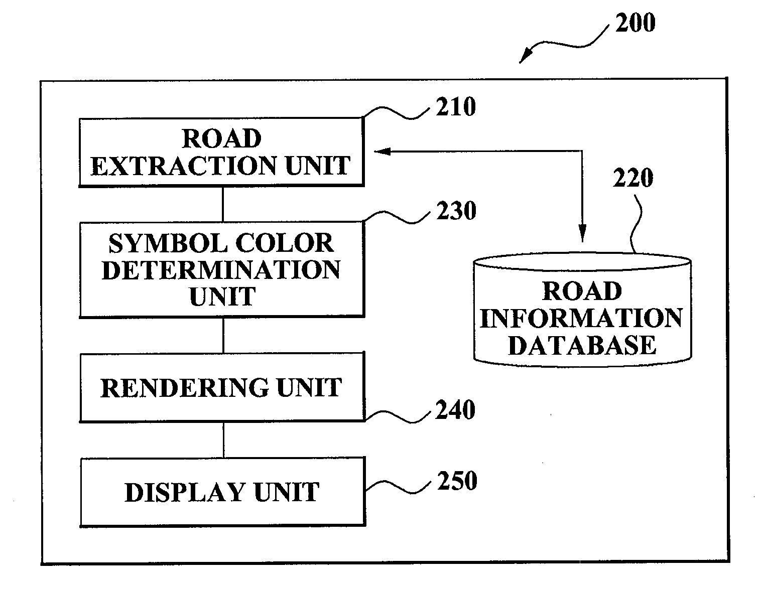
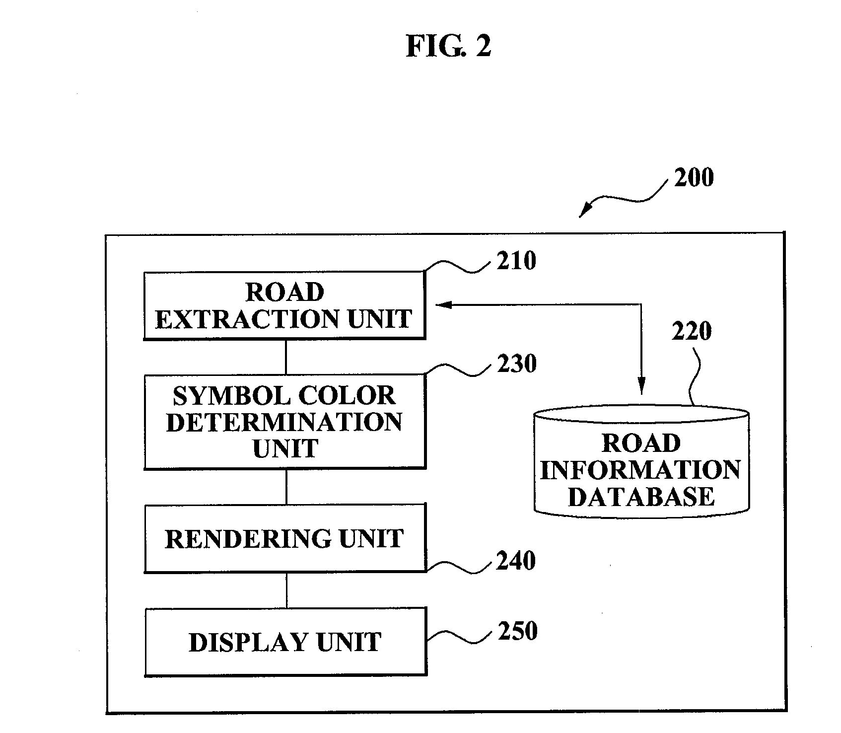
[0007]The present invention provides a method and system for displaying a driving location of a moving object which differently display information associated with a color of the moving object according to a road type where the moving object is driven, and thereby enable a user to easily notice a map-mismatching error of a map provided via a navigation service.
[0008]The present invention also provides a method and system for displaying a driving location of a moving object which determine a brightness value or a saturation value of a moving object symbol to be rendered according to a control of a Red, Green, Blue (RGB) ratio corresponding to a type of road where the moving object is driven, and thereby may enable a user to easily compare a road type which is displayed via a navigation service and the road type where a vehicle is actually driven.Technical Solutions

Problems solved by technology

However, navigation devices in a conventional art are susceptible to map-mismatching due to general errors in a GPS.
As an example, after a vehicle actually enters a tunnel, incorrect information may be provided showing that the vehicle is driven on a general roadway.

Method used


Image

  • Method and system for displaying traveling-position of move object
  • Method and system for displaying traveling-position of move object
  • Method and system for displaying traveling-position of move object

Examples


Embodiment Construction

[0018]Reference will now be made in detail to embodiments of the present invention, examples of which are illustrated in the accompanying drawings, wherein like reference numerals refer to the like elements throughout. The embodiments are described below in order to explain the present invention by referring to the figures.

[0019]A ‘moving object symbol’ in the present specification may refer to an icon, which represents a moving object on a guided road, in a navigation service providing navigation information from a starting location to a destination. For example, a symbol, a figure, a vehicle model, and the like, as the moving object symbol may be two-dimensionally or three-dimensionally rendered on the guided road. Through this, a user provided with the navigation service may accurately identify where the moving object is located on the road.

[0020]Particularly, according to the present invention, a brightness value or a saturation value of the moving object symbol to be rendered i...


PUM


Abstract

The present invention relates to a method and system for displaying a driving location of a moving object which controls a Red, Green, Blue (RGB) ratio by corresponding to a property of a road where the moving object travels, differently renders a moving object symbol according to the controlled RGB ratio, and thereby may identify a driving status of the moving object more accurately.

Description

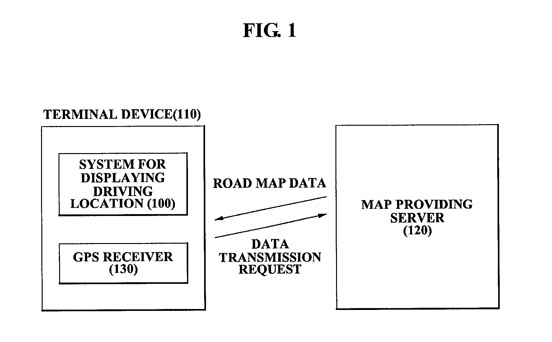
TECHNICAL FIELD[0001]The present invention relates to a method and system for displaying a driving location of a moving object which control a Red, Green, Blue (RGB) ratio by corresponding to a property of a road where the moving object is driven, differently render a moving object symbol according to the controlled RGB ratio, and thereby may identify a driving status of the moving object more accurately.BACKGROUND ART[0002]Generally, navigation devices providing navigation services receive Global Positioning System (GPS) signals from satellites and compute current locations of users by using the received GPS signals.[0003]Such navigation devices may ascertain current locations of vehicles. Accordingly, when vehicles arrive at points where navigation services are required, navigation services required at the points may be provided to users. For example, when a vehicle arrives at the point 100 meters away from a tunnel, navigation services such as ‘a tunnel 100 meters ahead’ may be p...

Claims


Application Information

Patent Timeline
Patent Type & Authority Patents(United States)
IPC IPC(8): G08G1/123
CPCG01C21/36G08G1/0969G01C21/32
Inventor SEONG, DEUK YEONG
Owner THINKWARE
Learn More