Deflectable catheter with distal deflectable segment

a technology of deflectable catheters and distal ends, which is applied in the field of catheters, can solve the problems of out-of-plane movement of the distal end, the deflecting movement of the distal tip may not be consistent between actuations, etc., and achieve the effect of enhancing or maximizing the lumen siz

Active Publication Date: 2011-07-26
ST JUDE MEDICAL ATRIAL FIBRILLATION DIV
View PDF3 Cites 32 Cited by
  • Summary
  • Abstract
  • Description
  • Claims
  • Application Information

AI Technical Summary

Benefits of technology

[0016]In another aspect, a guidable catheter is provided having a distal deflectable segment formed of a first material and at least one stiffening material formed of a second material. In a non-deflected state, the deflectable segment is substantially tubular, and the length of the deflectable segment defines a reference longitudinal axis. The stiffening element is incorporated into a sidewall of the deflectable segment and extends over at least a portion of the length of the deflectable segment. In such an arrangement, the distal deflectable segment may define an internal lumen that may be substantially free of intrusion by the stiffening element. That is, in one arrangement, the stiffening element may be fully encapsulated within the sidewall. This may enhance or maximize the size of the lumen for fluid passage and / or passage of devices through the lumen.

Problems solved by technology

However, due to the previous construction of distal deflectable segments, the tip of the catheter is often able to move out of the desired sweeping plane.
That is, it has been determined that deflecting movement of the distal tip may not be consistent between actuations.
However, it will be appreciated that due to the high bending stiffness for deflection in the reinforced plane, minor misplacement of the pull wire(s) away from the sweeping plane may not result in out-of-plane movement of the distal end of the catheter body upon deflection of the deflectable segment.

Method used


Image

  • Deflectable catheter with distal deflectable segment
  • Deflectable catheter with distal deflectable segment
  • Deflectable catheter with distal deflectable segment

Examples


Embodiment Construction

[0031]Exemplary embodiments of a catheter system and methods of using the system to access internal areas of interest are depicted in the figures. As described further below, use of a catheter having a distal deflectable segment having anisotropic bending properties allows for improved catheter guidance and / or improved control for tissue access / contact.

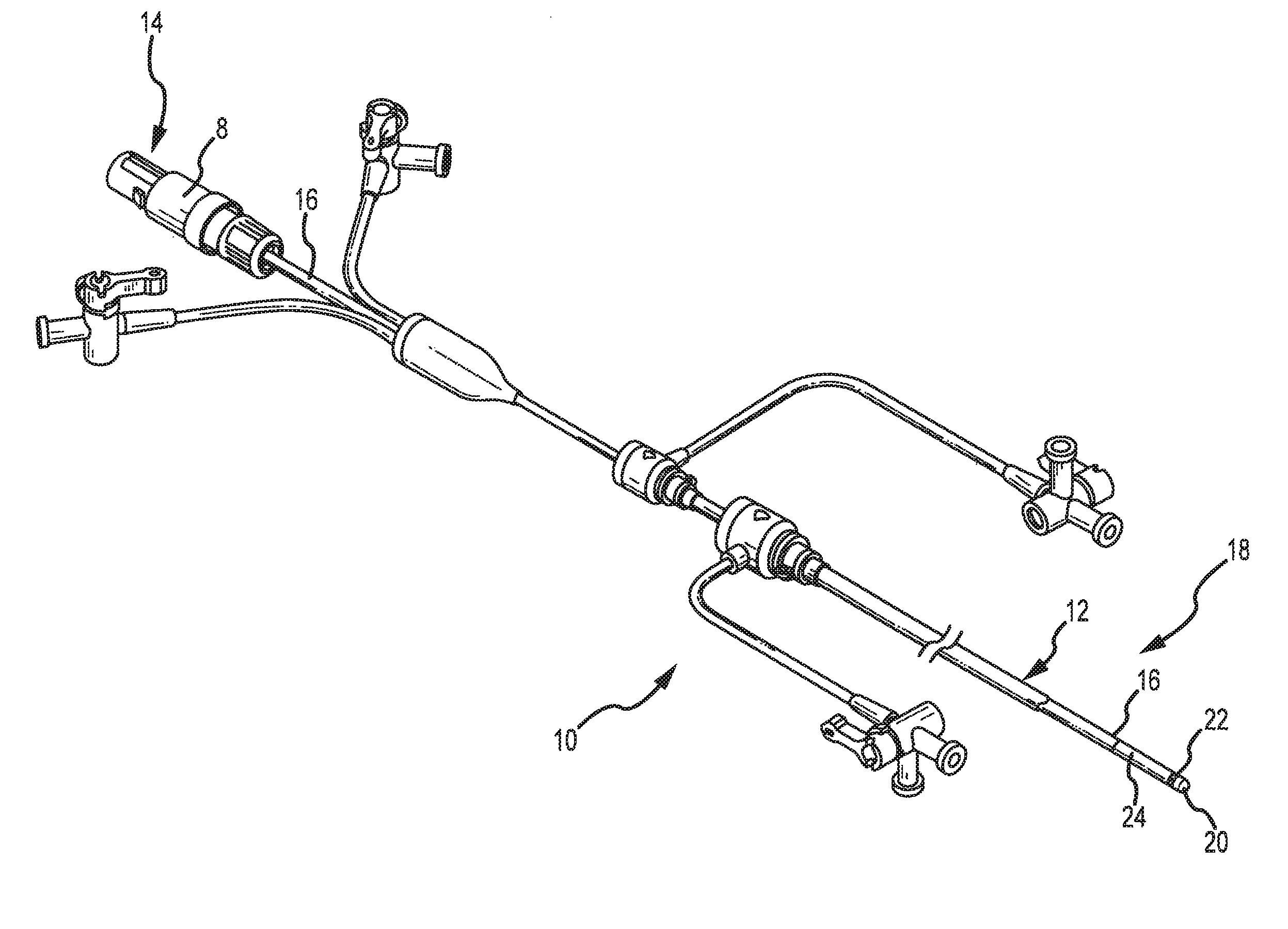
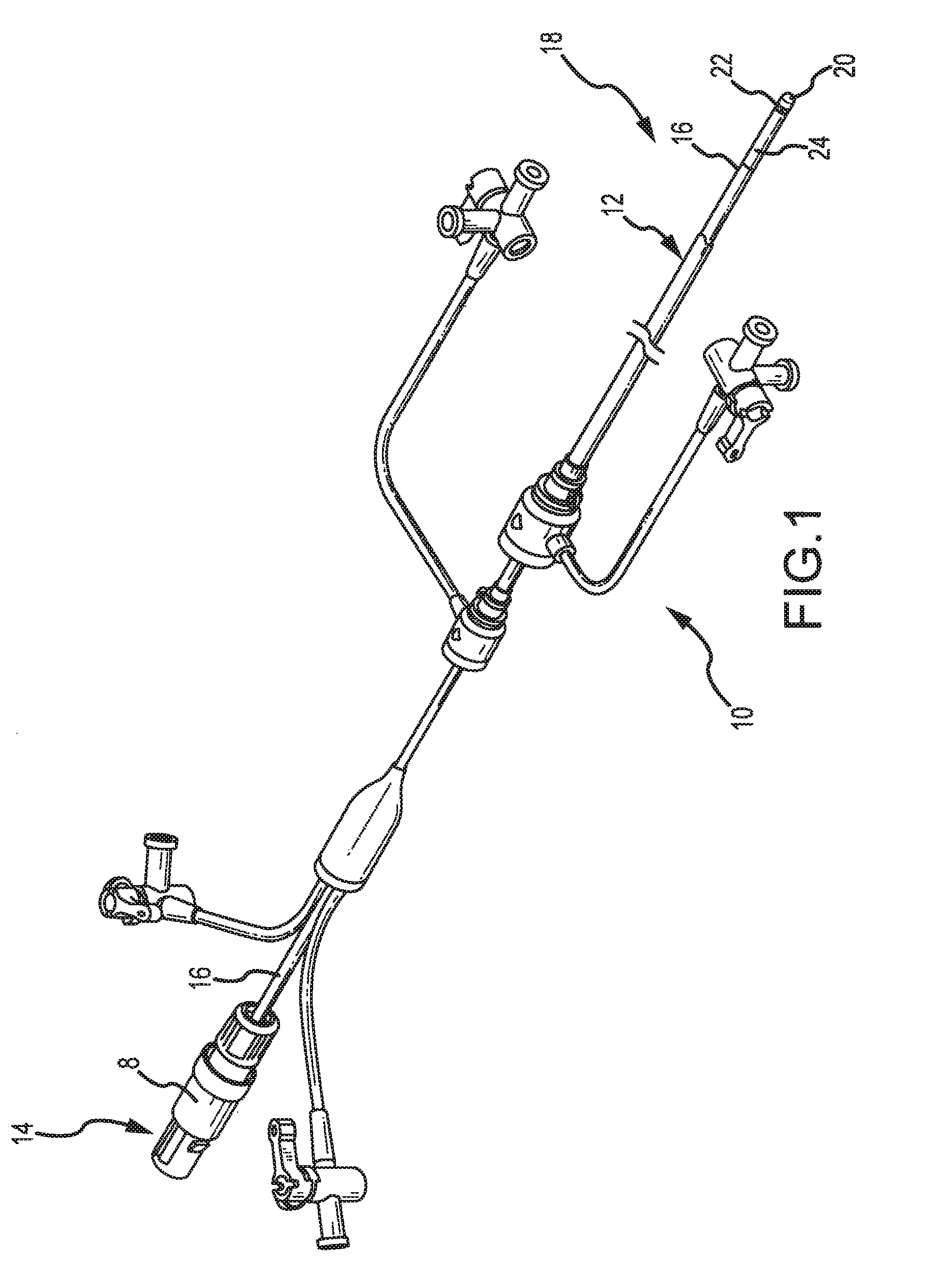
[0032]FIG. 1 illustrates an exemplary electrode catheter system that may be utilized to access, map and / or perform medical procedures on internal tissue of interest. The catheter system 10 may include a guiding introducer having a sheath 12, which may be inserted into a patient. The sheath 12 may provide a lumen for the introduction of a catheter 18 which may be disposed beyond the distal insertion end of the sheath 12. In the particular configuration of FIG. 1, the sheath 12 is configured to receive and guide the catheter 18 to an internal location in the heart once the sheath is pre-positioned in an appropriate location. During an e...


PUM


Abstract

A guidable, or steerable, or deflectable catheter is provided that includes a proximal portion and a distal portion for insertion into a body cavity. A selectively deflectable segment having an anisotropic bending stiffness for deflection in individual planes is incorporated into the distal portion of the catheter shaft. Upon actuation of pull wires, the distal deflectable segment may be deflected to move / sweep the distal catheter tip through a sweeping plane. The anisotropic bending stiffness of the distal deflectable segment permits in-plane movement of the distal catheter tip in the sweeping plane while resisting any out-of-plane movements. In one arrangement, stiffening elements are selectively disposed within the distal deflectable segment such that the out-of-plane bending stiffness is largely increased and greater than the in-plane bending stiffness for deflection in the sweeping plane. In another arrangement, the cross section of a distal deflectable segment is altered to produce anisotropic area inertias of moment about its centroidal axes, and thus anisotropic bending stiffnesses.

Description

BACKGROUND OF THE INVENTION[0001]a. Field of the Invention[0002]The invention generally relates to catheters for guided introduction into a body cavity. More specifically, the invention relates to a catheter that includes a distal deflectable segment having an anisotropic deflecting (or bending) stiffness that reduces or eliminates unintended out-of-plane movement of a distal end of the catheter.[0003]b. Background Art[0004]Catheters can be used for medical procedures to examine, diagnose, and treat while positioned at a specific location within the body that is otherwise inaccessible without more invasive procedures. During these procedures a catheter is typically inserted into a vessel near the surface of the body and is guided to a specific location within the body for examination, diagnosis, and treatment. For example, catheters can be used to convey an electrical stimulus to a selected location within the human body, e.g., for tissue ablation, as well as to monitor various form...

Claims


Application Information

Patent Timeline
Patent Type & Authority Patents(United States)
IPC IPC(8): A61M25/00
CPCA61M25/0052A61M25/0144A61M25/0147A61B5/042A61B18/1492A61B2017/003A61B5/283
Inventor GUO, XIAOPINGTEGG, TROY T.STEHR, RICHARD E.
Owner ST JUDE MEDICAL ATRIAL FIBRILLATION DIV
Why Eureka
Try Eureka