AI technical title is built by Patsnap AI team. It summarizes the technical point description of the patent document.
a technology of dimmer switch and switch body, which is applied in the direction of lighting and heating apparatus, heating types, instruments, etc., can solve the problem that the integration of multiple control features in a single device typically requires more complicated manufacturing processes to accommodate the different features
Inactive Publication Date: 2011-07-26
LEVITON MFG
View PDF100 Cites 15 Cited by
Summary
Abstract
Description
Claims
Application Information
AI Technical Summary
This helps you quickly interpret patents by identifying the three key elements:
Problems solved by technology
Method used
Benefits of technology
Problems solved by technology
While it is now commonplace for devices to control a plurality of states, such as the ON / OFF / DIM / BRIGHT state of a lighting load, the integration of multiple control features in a single device typically requires more complicated manufacturing processes to accommodate the different features.
Method used
Image
Click on the blue label to locate the original text in one second.
Reading with bidirectional positioning of images and text.
Examples
Embodiment Construction
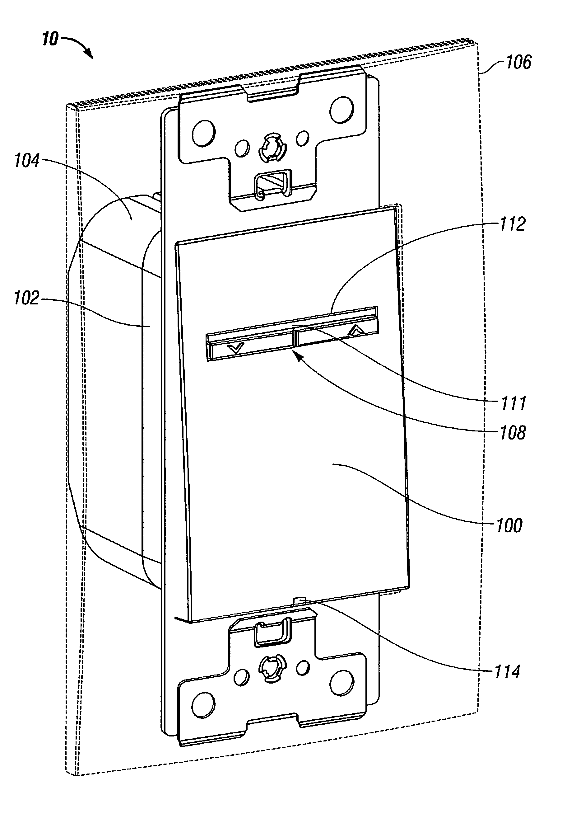
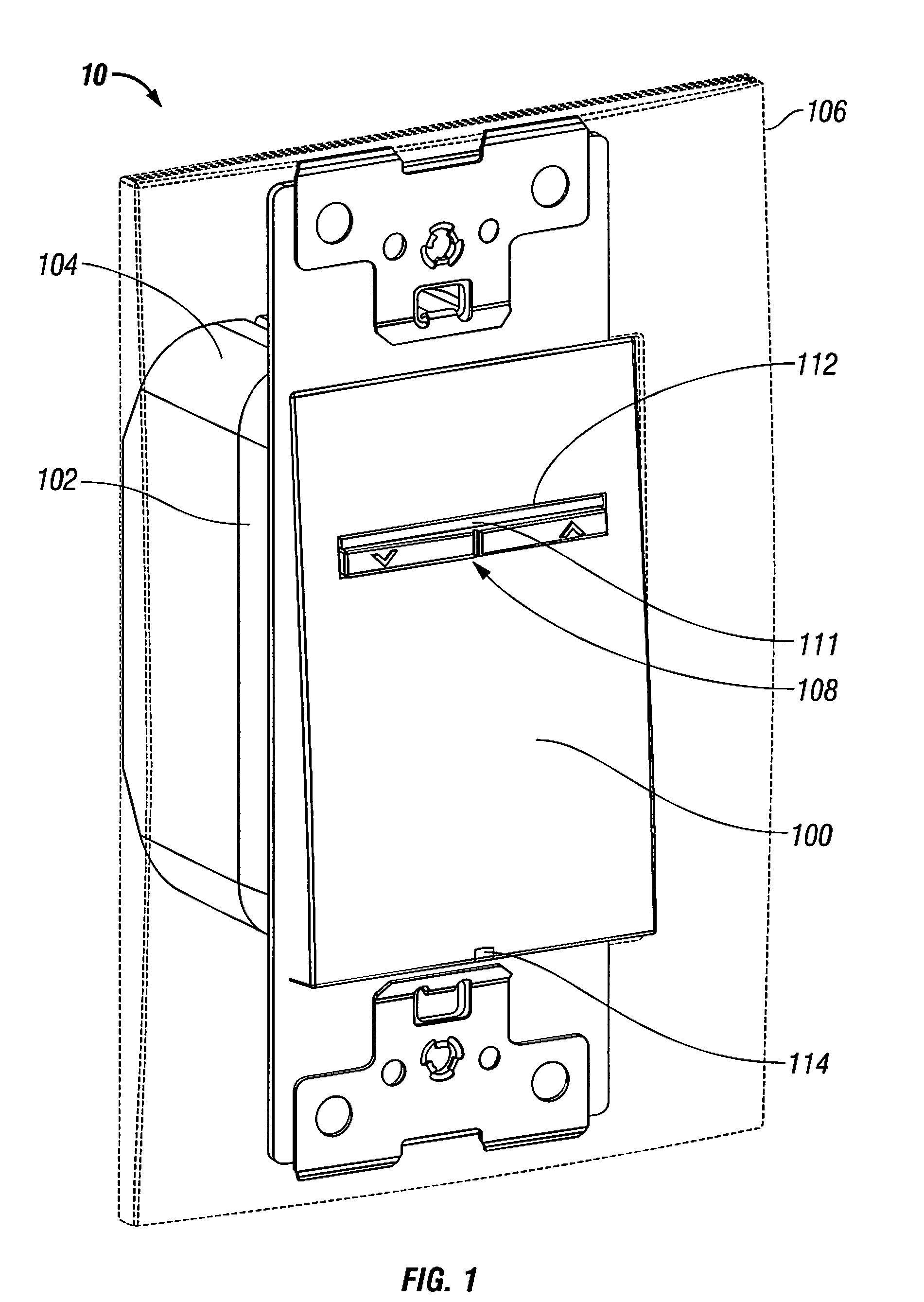
[0021]Particular embodiments of the present disclosure are described hereinbelow with reference to the accompanying drawings wherein like reference numerals identify similar or identical elements. In the following description, well-known functions or constructions are not described in detail to avoid obscuring the present disclosure in unnecessary detail.
[0022]The switching device described herein in accordance with the present disclosure relates to a dimmer-like switch characterized by a large paddle actuator having an intensity actuator embedded therein. The paddle actuator is substantially rectangular in shape having a pair of opposing long sides and top and bottom short sides. The paddle actuator is biased to a rest position by a one or more springs (e.g., leaf springs) formed in a sub-panel below the paddle. A user may press the paddle to overcome the bias and cause the paddle to rotate about one or more pivots to a depressed position wherein an ON / OFF switch is actuated. When ...
PUM
Abstract
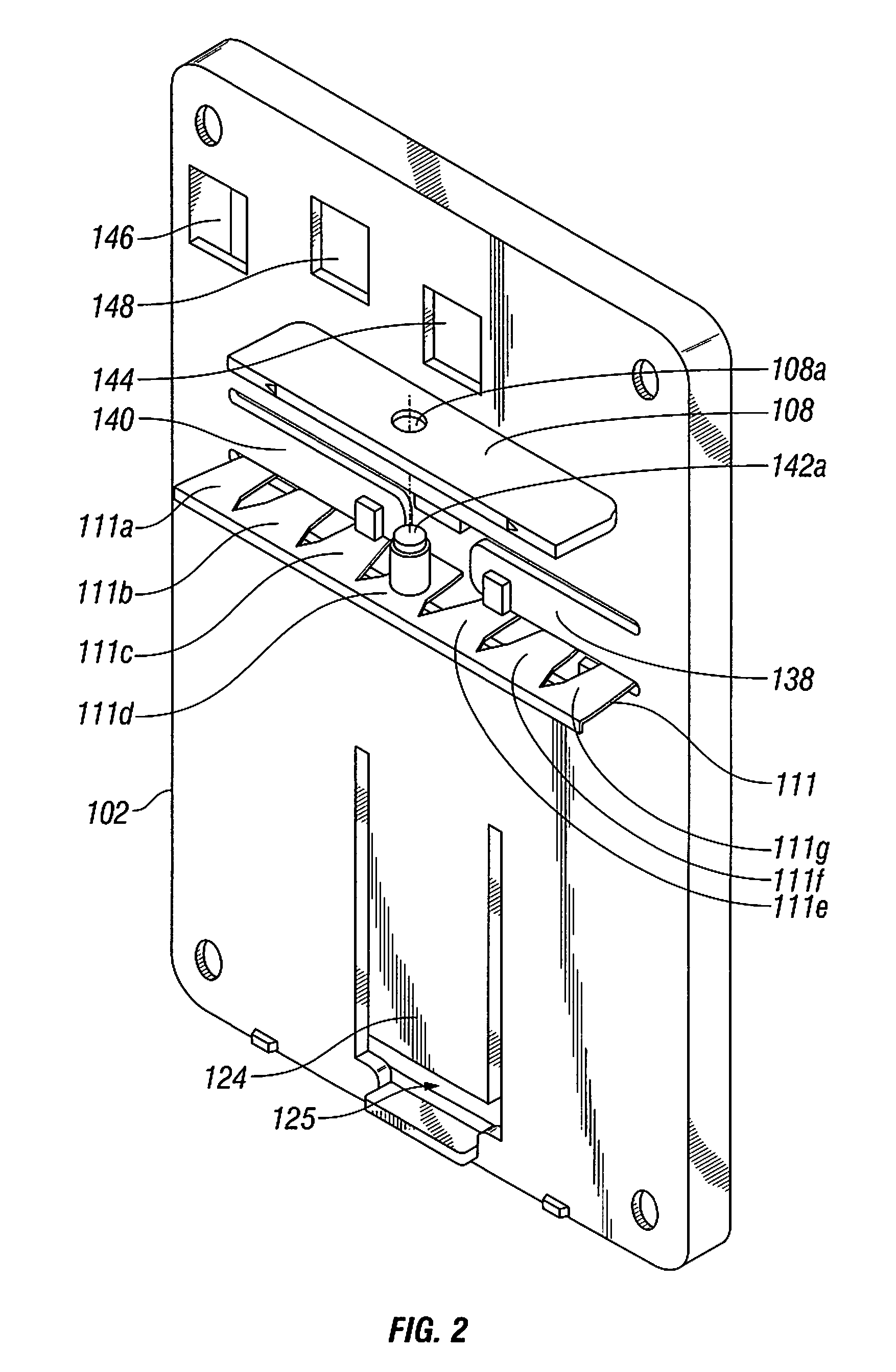
A switching device includes a paddle actuator biased to a rest position and configured to pivot relative to a housing to a depressed position to engage an air-gap switch disposed within the housing. The air-gap switch is configured to change a first state of a load connected to the switching device upon engagement by the paddle actuator. The paddle actuator is defined by a pair of opposing long sides and a pair of opposing short sides and has at least one slot defined therein parallel to the pair of opposing short sides thereof and centrally disposed between the pair of opposing long sides thereof. A rocker actuator is disposed in the at least one slot defined in the paddle actuator and is configured to pivot relative thereto to engage at least one switch. The at least one switch is configured to change a second state of the load connected to the switching device upon engagement by the rocker actuator.
Description
CROSS REFERENCE TO RELATED APPLICATIONS[0001]This application claims priority to Provisional patent application entitled “DIMMER SWITCH” filed in the United States Patent and Trademark Office on Jul. 18, 2007 and assigned Ser. No. 60 / 961,188, and relates to U.S. Pat. Nos. D534,875, D517,999, D518,000, D519,466, D526,624, D542,230, D543,159, D535,627, D534,873, 7,170,018, and U.S. Patent Publication No. 2006 / 0125649, the entire contents of all of which being incorporated by reference herein.BACKGROUND[0002]1. Technical Field[0003]The present invention relates to a switching device used to control electrical systems and / or devices and, more particularly, relates to a switch for selectively adjusting or varying a state of a current load.[0004]2. Description of Related Art[0005]Switches and controls for electrical systems and devices have been developed that control more than one state of an electrical load or device. While it is now commonplace for devices to control a plurality of sta...
Claims
Application Information
Patent Timeline
Application Date:The date an application was filed.
Publication Date:The date a patent or application was officially published.
First Publication Date:The earliest publication date of a patent with the same application number.
Issue Date:Publication date of the patent grant document.
PCT Entry Date:The Entry date of PCT National Phase.
Estimated Expiry Date:The statutory expiry date of a patent right according to the Patent Law, and it is the longest term of protection that the patent right can achieve without the termination of the patent right due to other reasons(Term extension factor has been taken into account ).
Invalid Date:Actual expiry date is based on effective date or publication date of legal transaction data of invalid patent.
Patent Type & AuthorityPatents(United States)
IPC IPC(8): H01H9/00F24F11/00
CPCH01H9/0271H01H23/025H01H23/26
InventorWU, YUNLOMBARDI, ALFRED J.CHOU, CHENG-LUNGILKHANOV, AZER

