Safety razor with multi-pivot blade unit

a safety razor and multi-pivot technology, applied in the field of safety razors, can solve the problem that the blade unit is often disengaged from the skin, and achieve the effect of avoiding disengagemen

Active Publication Date: 2011-03-29
THE GILLETTE CO
View PDF51 Cites 82 Cited by
  • Summary
  • Abstract
  • Description
  • Claims
  • Application Information

AI Technical Summary

Benefits of technology

[0012]Advantageously the magnetic elements which produce the first and second return forces are so arranged that as the angle of pivoting about the first and second pivot axes from the first and second rest position increases, the spring rate characteristic of the magnetic return force increases smoothly. A further advantage of the invention is that the strength of the return forces can easily be modified by using magnetic elements of different magnetic strength.
[0013]The first pivot axis is preferably positioned to be substantially perpendicular to the second pivot axis.
[0014]Although the magnetic elements can conveniently be permanent magnets, at least one of the magnetic elements can comprise an electromagnetic element, in which case a control device can be provided for adjusting the electric magnetizing current delivered to the electromagnetic element. A sensor may, for example, be provided to sense the pivotal displacement of the blade unit from the rest position and the control device can be responsive to an output from the sensor.
[0015]The second set of magnetic elements preferably comprises a third magnetic element, a fourth magnetic element and a fifth magnetic element. The second set of magnetic elements may comprise a sixth magnetic element.
[0016]The third magnetic element may be mounted to the handle and the fourth and fifth magnets may be mounted to the blade unit. Alternatively, the third magnetic element may be mounted to the blade unit and the fourth and fifth magnets may be mounted to the handle.

Problems solved by technology

However, the blade unit often disengages from the skin during shaving as it has limited ability to pivot about a single axis.

Method used


Image

  • Safety razor with multi-pivot blade unit
  • Safety razor with multi-pivot blade unit
  • Safety razor with multi-pivot blade unit

Examples


Embodiment Construction

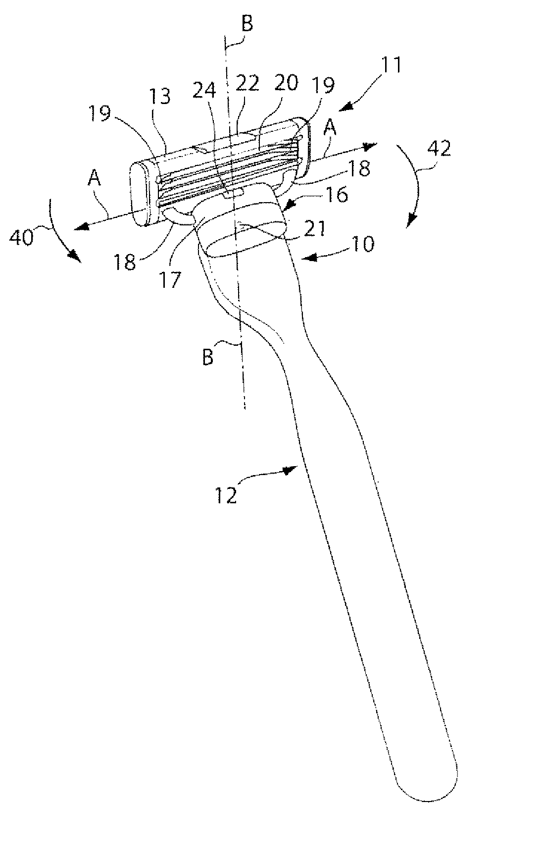
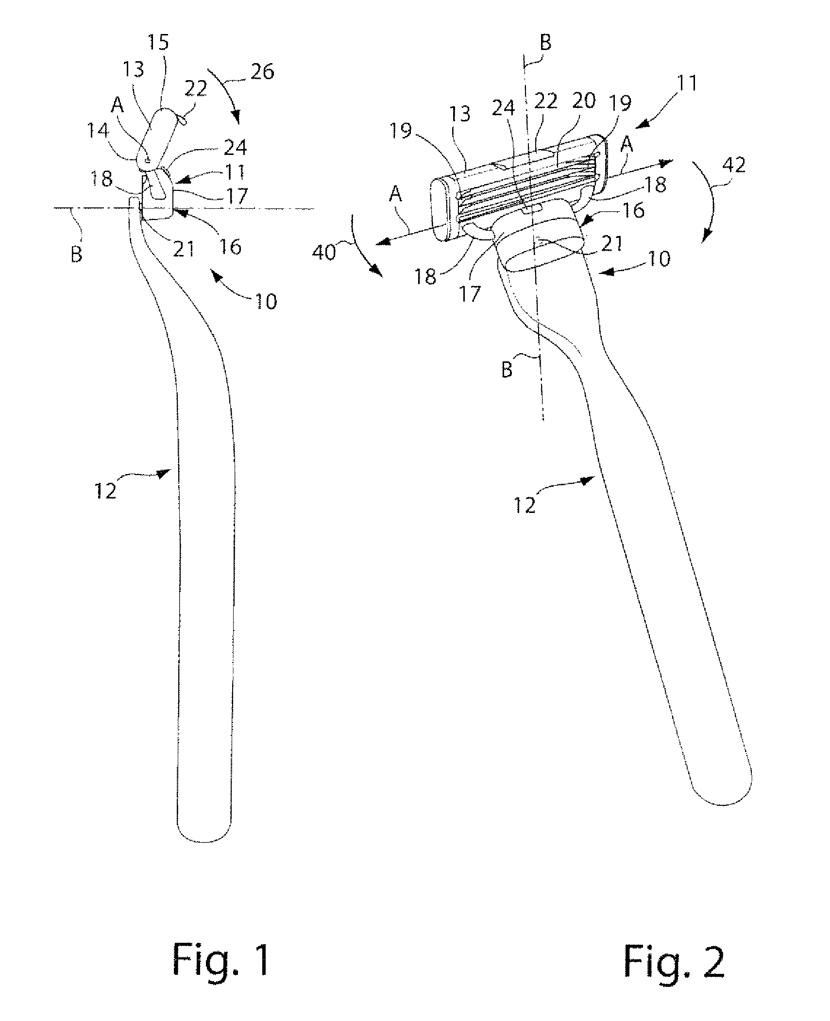
[0026]The safety razor 10 illustrated in FIGS. 1-4 has a blade unit 11 mounted on a handle 12. The blade unit 11 includes a frame 13 with a guard 14 and a cap 15 and a plurality of blades 20 positioned between the guard 14 and cap 15 with their cutting edges parallel to each other, as well known in the art.

[0027]The blades 20 are movable independently of each other and are urged upwardly with respect to a plane tangential to the guard 14 and cap 15 surfaces by springs 19 which determine the force of the blades against the skin during shaving. The guard 14 preferably includes a strip of elastomeric material with projections such as fins, and the cap 15 may comprise a strip for applying a shaving enhancement product for the skin as previously known.

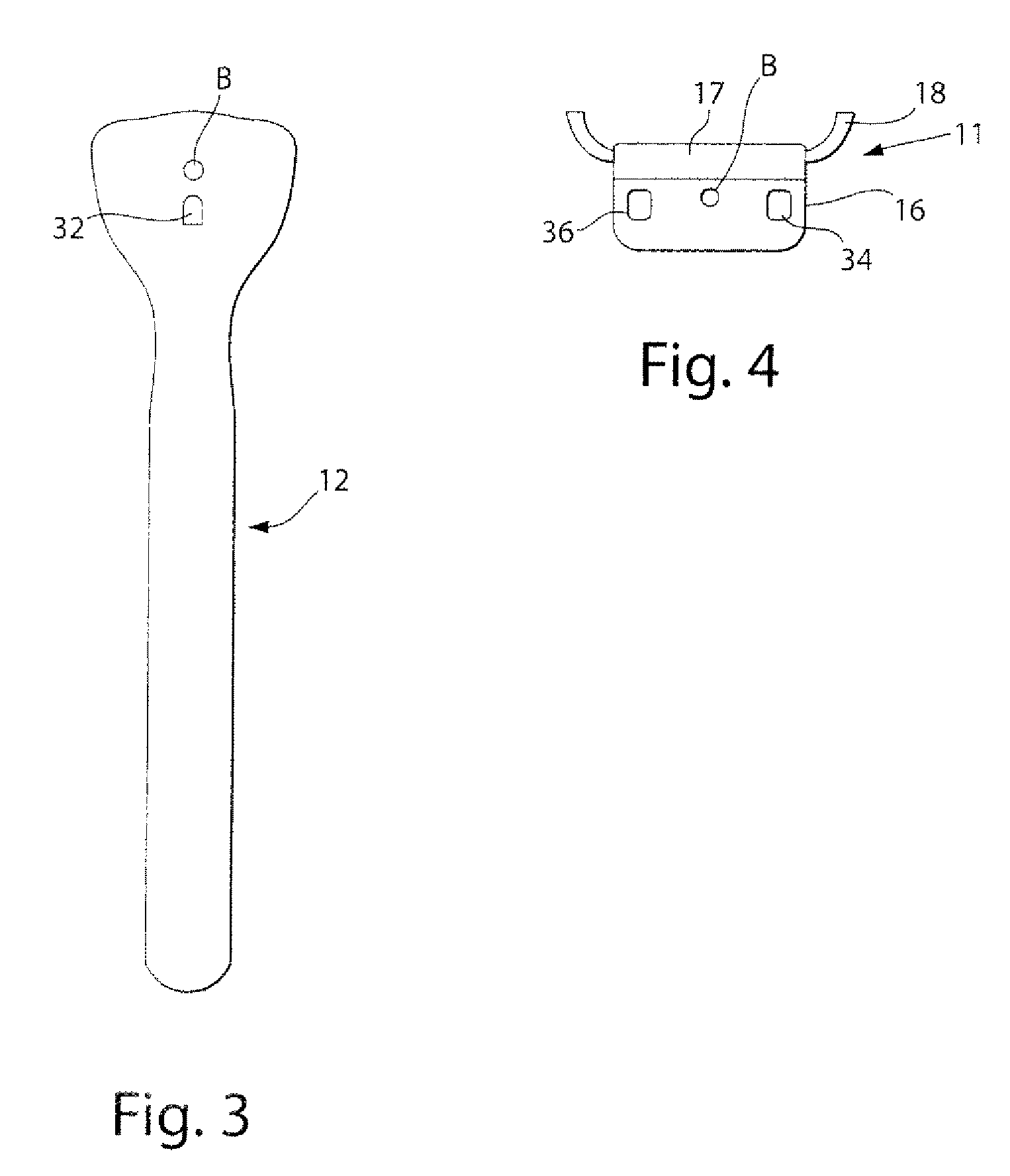
[0028]The blade unit 11 is provided with an attachment member 16 including a hub 17. Attachment member 16 of blade unit 11 is pivotally attached to handle 12 via pin 21. The hub 17 is detachably clipped onto attachment member 16. Hub 17 inc...


PUM

PropertyMeasurementUnit
magnetic forceaaaaaaaaaa
repulsive magnetic return forceaaaaaaaaaa
magneticaaaaaaaaaa

Abstract

A safety razor blade unit mounted for pivotal movement relative to a razor handle about a pivot axis substantially perpendicular to a blade mounted in the blade unit. The blade unit is biased to a rest position by a magnetic return force generated by a set of magnetic elements. The set of magnetic elements are so disposed that the return force increases as the pivotal displacement of the blade unit from the rest position increases.

Description

FIELD OF THE INVENTION[0001]This invention relates to safety razors and it is particularly concerned with safety razors in which a safety razor blade unit including at least one blade with a sharp cutting edge is mounted on a razor handle to be movable pivotally relative to the handle under forces exerted on the blade unit in the course of shaving. A blade unit may have a plurality of blades, for example two, three, four or more blades, with straight parallel cutting edges disposed for contact with the skin between guard and cap surfaces also provided on the blade unit. The guard may include a strip of elastomeric material with a surface configuration, for example upstanding projections such as in the shape of fins, to produce a desired interaction with the skin as the blade unit is moved across the skin in the performance of a shaving stroke. The cap surface may include a strip of material containing a shaving enhancement product, such as a lubricant, which can gradually leach out ...

Claims


Application Information

Patent Timeline
Patent Type & Authority Patents(United States)
IPC IPC(8): B26B21/00
CPCB26B21/225B26B21/40B26B21/52Y10T83/9459
Inventor ROYLE, TERENCE GORDONFORSDIKE, EDWARD NEILL
Owner THE GILLETTE CO
Why Eureka
Try Eureka