Low frequency electromagnetic motor to create or cancel a low frequency vibration

a low frequency electromagnetic and motor technology, applied in the direction of magnets, mechanical energy handling, magnetic bodies, etc., can solve the problems of uneven spring load, frequent service, and application of this device in an audio system

Inactive Publication Date: 2010-12-28
EARTHQUAKE SOUND
View PDF37 Cites 82 Cited by
  • Summary
  • Abstract
  • Description
  • Claims
  • Application Information

AI Technical Summary

Benefits of technology

[0012]Electromagnetic motor with a piston that moves linearly with respect to the stator in either direction. Embodiments include a piston internal or external the stator. The piston includes one or more magnetic flux producing elements in all embodiments, with some embodiments having a ferro-magnetic plate on either side of the flux producing element. Further, in all embodiments the stator includes three magnetic flux producing elements with either two coils with one or more magnets therebetween or with the two coils and a coil magnet substitute therebetween. All embodiments provide positive piston return to a center at rest position. In all embodiments the piston is centered with respect to the stator resulting from either magnetic interaction between the piston and stator magnets, or between the piston magnet and the stator magnet substitute coil.

Problems solved by technology

The use of springs in this design, requires frequent service as the spring constant tends to change with time.
Additionally, as the moving element moves the springs tend to make noise that is audible when the actuator is in use making application of this device unacceptable in an audio system as a low frequency radiator.
Also, if the actuator is mounted vertically with the centering shaft oriented vertically, the weight of the moving element will exercise an uneven load on the springs.
This misalignment will create heat, reduction of performance and possibly destruction of the actuator.
The “flexure” in this design in simple terms is a spring and thus this design has problems that are similar to those described above with respect to patent '336.
r OFF. Once again this design does not address centering during vertical mounting as gravity will offset the center slider causing it to have very poor performance, heat up and then malfu
These and other previous designs each include drawbacks to various applications of the device disclosed.
These complex designs produce spring noise, spring fatigue and require a complex assembly.
That design suffers from short strokes since the excursion of the slider is directly related to the distance between the coils.
Another weakness of prior art designs is that they do not offer linear resistance to the slider throughout the path of movement, i.e., the further the slider travels from the center position, the less resistance there is in the direction of movement.
These designs only help centering of the slider when in the non-actuated position with the vibration that they produce being non linear and devices designed in these ways simply providing little more than on-off type compliance.

Method used


Image

  • Low frequency electromagnetic motor to create or cancel a low frequency vibration
  • Low frequency electromagnetic motor to create or cancel a low frequency vibration
  • Low frequency electromagnetic motor to create or cancel a low frequency vibration

Examples


first embodiment

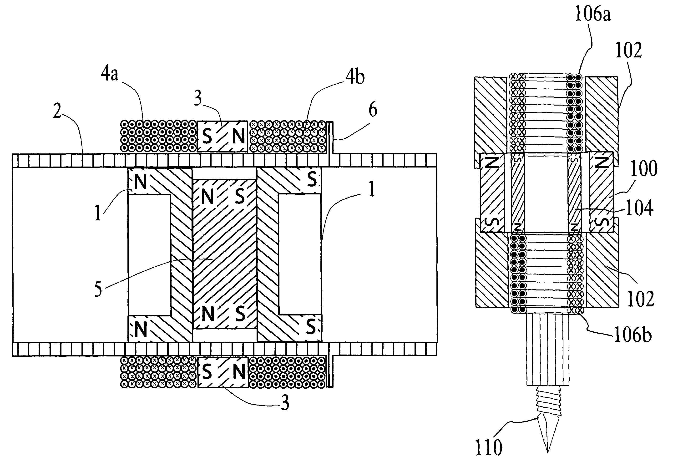
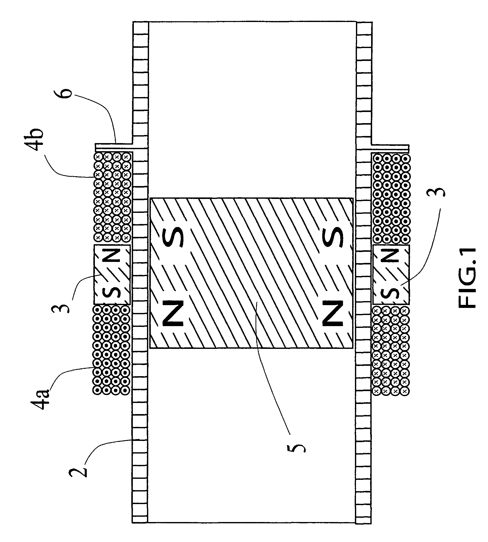
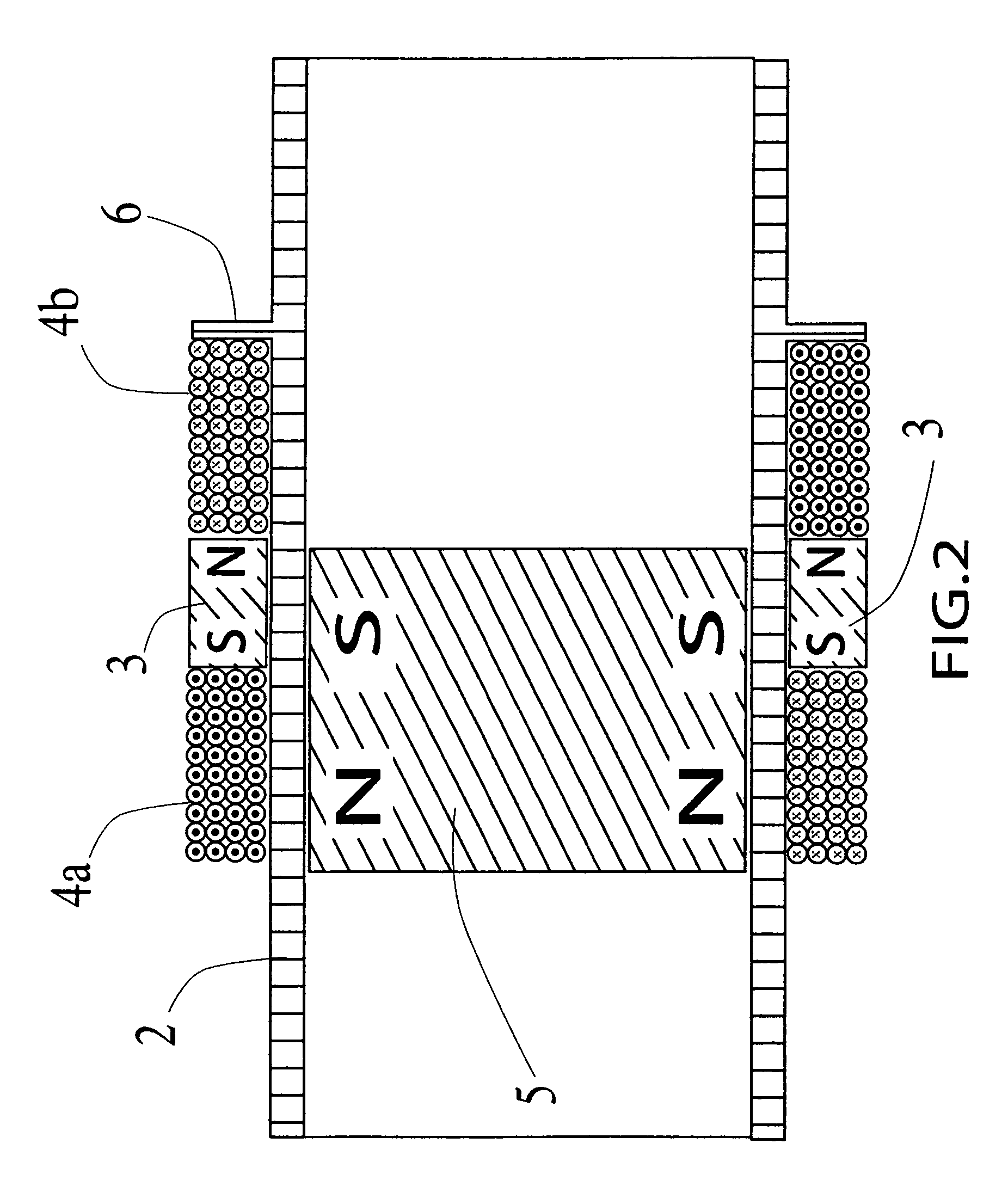
[0028]FIGS. 1 and 2 illustrate the present invention in a longitudinal cross-sectional view of the electromagnetic motor. Looking first at FIG. 1, the stator of the electromagnetic motor includes a tube 2 of a non-ferrous (non-magnetic) material (e.g., aluminum, plastic, etc.) that has a selected length and inner diameter. The ends of tube 2 are shown open, however a non-ferrous cap can be placed on each end to prevent foreign material from entering tube 2 which could imped the free movement of the piston. Additionally, a hollow core magnet 3 (i.e., a doughnut magnet) is substantially centered longitudinally on the outside of tube 2 with the diameter of the center hole in magnet 3 being substantially the same as the outer diameter of tube 2. Further, wound around the outside of tube 2, on opposite sides of magnet 3, are two electrically conductive coils 4a and 4b (i.e., inductors or voice coils) each next to, or equally spaced apart from (FIG. 5), the sides of magnet 3. Also shown i...

second embodiment

[0038]Experimental results point to the best design for the second embodiment being: the inclusion of a thin walled tube 2 to yield cooler operation and a stronger magnetic flux coupling between the stator and the piston; magnets 3 and 5 being substantially equal in width; each of plates 1 having substantially the same width as magnet 5 (i.e., a piston width that is three times the width of magnet 5); coils 4a and 4b being equal to each other in width and inductive value; each of coils 4a and 4b having a width that is approximately 20% greater than the width of a single plate 1; and the strength of the signals applied to coils 4a and 4b being such to cause each of the coils to generate a magnetic field of equal strength, thus if coils 4a and 4b are as described above (i.e., of equal width and equal inductive value then the signals would be substantially the same thus permitting coils 4a and 4b to be wired in series, while maintaining the reverse winding as shown, and a single signal...

third embodiment

[0044]As in previous embodiments as illustrated in the respective figures, FIG. 7 is a horizontal cross-section of the third embodiment with the piston at the furthest travel point to the left with a maximum steady-state signal on stator windings 4a and 4b.

[0045]With the stator components in a configuration as shown in FIGS. 6 and 7, experimental results indicate that the best performance is achieved when the sum of the widths of spacers 10b, 10c and 10d, and the widths of magnets 9a and 9b is substantially equal to the width of one of coils 4a and 4b where the widths of coils 4a and 4b are substantially the same as each other.

[0046]FIG. 8 is a horizontal cross-section of a modified third embodiment with the piston at the furthest travel point to the left with a maximum steady-state signal on stator windings with the piston only having magnets 11 without plates 1 that are shown in FIGS. 6 and 7.


PUM


Abstract

Electromagnetic motor with a piston that moves linearly with respect to the stator in either direction. Embodiments include a piston internal or external the stator. The piston includes one or more magnetic flux producing elements in all embodiments, with some embodiments having a ferro-magnetic plate on either side of the flux producing element. Further, in all embodiments the stator includes three magnetic flux producing elements with either two coils with one or more magnets therebetween or with the two coils and a coil magnet substitute therebetween. All embodiments provide positive piston return to a center at rest position. In all embodiments the piston is centered with respect to the stator resulting from either magnetic interaction between the piston and stator magnets, or between the piston magnet and the stator magnet substitute coil.

Description

CROSS-REFERENCE[0001]This application is related to an application by the same applicant having Ser. No. 11 / 086,216 filed Mar. 21, 2005 for Electromagnetic Motor to Create a Desired Low Frequency Vibration or to Cancel an Undesired Low Frequency Vibration.BACKGROUND OF THE INVENTION[0002]1. Field of the Invention[0003]The present invention relates to a linear stroke electromagnetic motor having a movable internal mass that is caused to move selectively by the application of electrical signals to external coils to create an electromagnetic force on the movable internal mass to produce a desired low frequency sound or strong variable vibration or to drive a solenoid like apparatus proportionally to the applied signals.[0004]2. Description of the Prior Art[0005]The prior art includes various linear stroke electromagnetic motors. An early such device is disclosed in U.S. Pat. No. 4,542,311 (hereinafter '311), issued Sep. 17, 1985 and entitled LONG LINEAR STROKE RECIPROCATING ELECTRIC MA...

Claims


Application Information

Patent Timeline
Patent Type & Authority Patents(United States)
IPC IPC(8): H02K33/12H02K33/18
CPCH02K33/16
Inventor SAHYOUN, JOSEPH Y
Owner EARTHQUAKE SOUND
Why Eureka
Try Eureka