OFDM frequency scanning radar

a frequency scanning and radar technology, applied in the field of radar systems, can solve problems such as limited range resolution, and achieve the effect of increasing angular resolution

Active Publication Date: 2011-08-09
RGT UNIV OF MICHIGAN
View PDF23 Cites 23 Cited by
  • Summary
  • Abstract
  • Description
  • Claims
  • Application Information

AI Technical Summary

Problems solved by technology

The range resolution is limited by the instantaneous signal bandwidth of the radar sensor in both pulse-Doppler and FMCW radars.

Method used


Image

  • OFDM frequency scanning radar
  • OFDM frequency scanning radar
  • OFDM frequency scanning radar

Examples


Embodiment Construction

[0035]The following description is merely exemplary in nature and is in no way intended to limit the disclosure, its application, or uses. For purposes of clarity, the same reference numbers will be used in the drawings to identify similar elements. As used herein, the phrase at least one of A, B, and C should be construed to mean a logical (A or B or C), using a non-exclusive logical or. It should be understood that steps within a method may be executed in different order without altering the principles of the present disclosure.

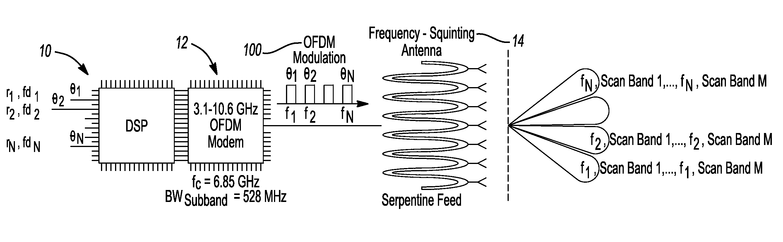
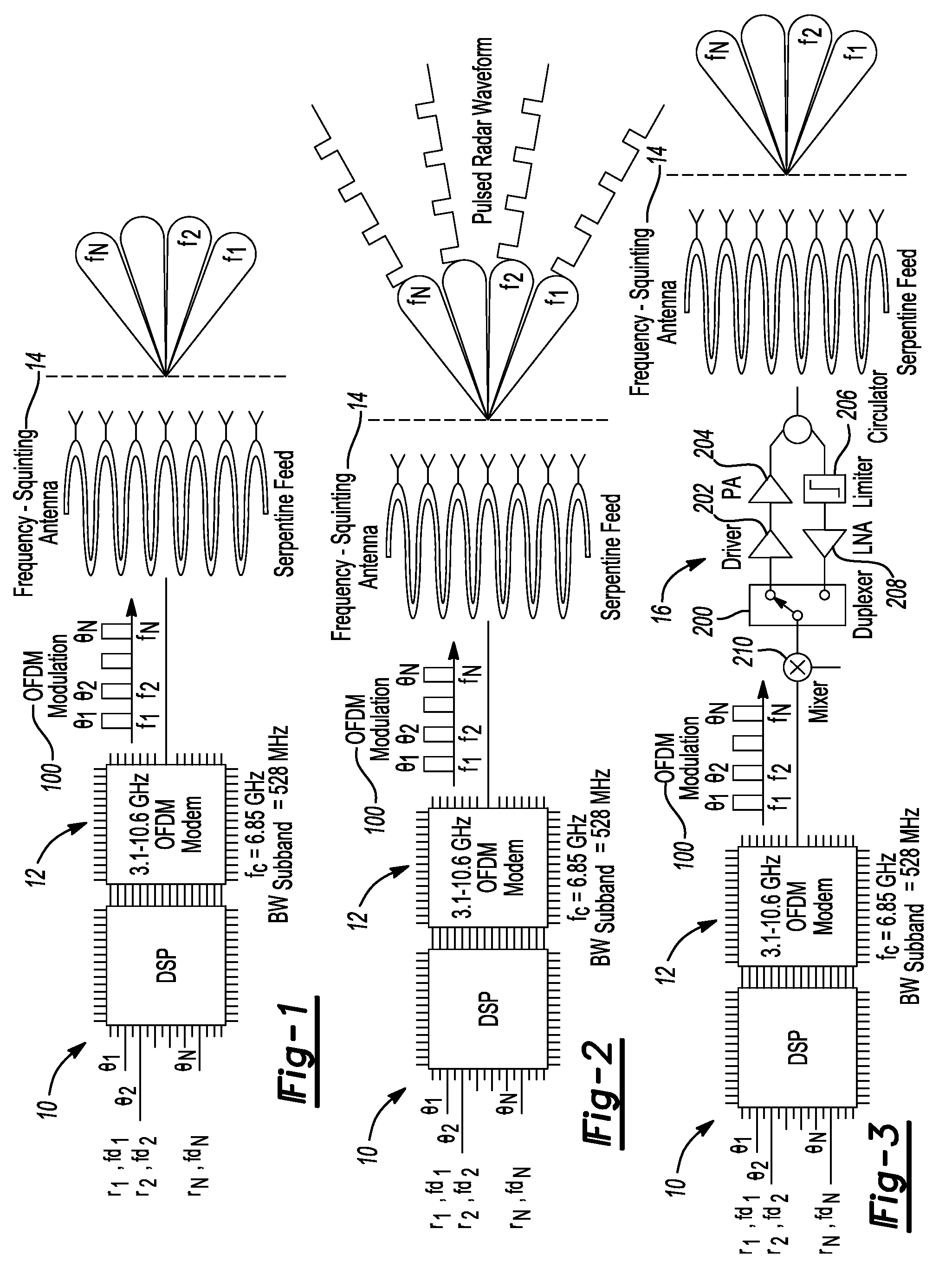
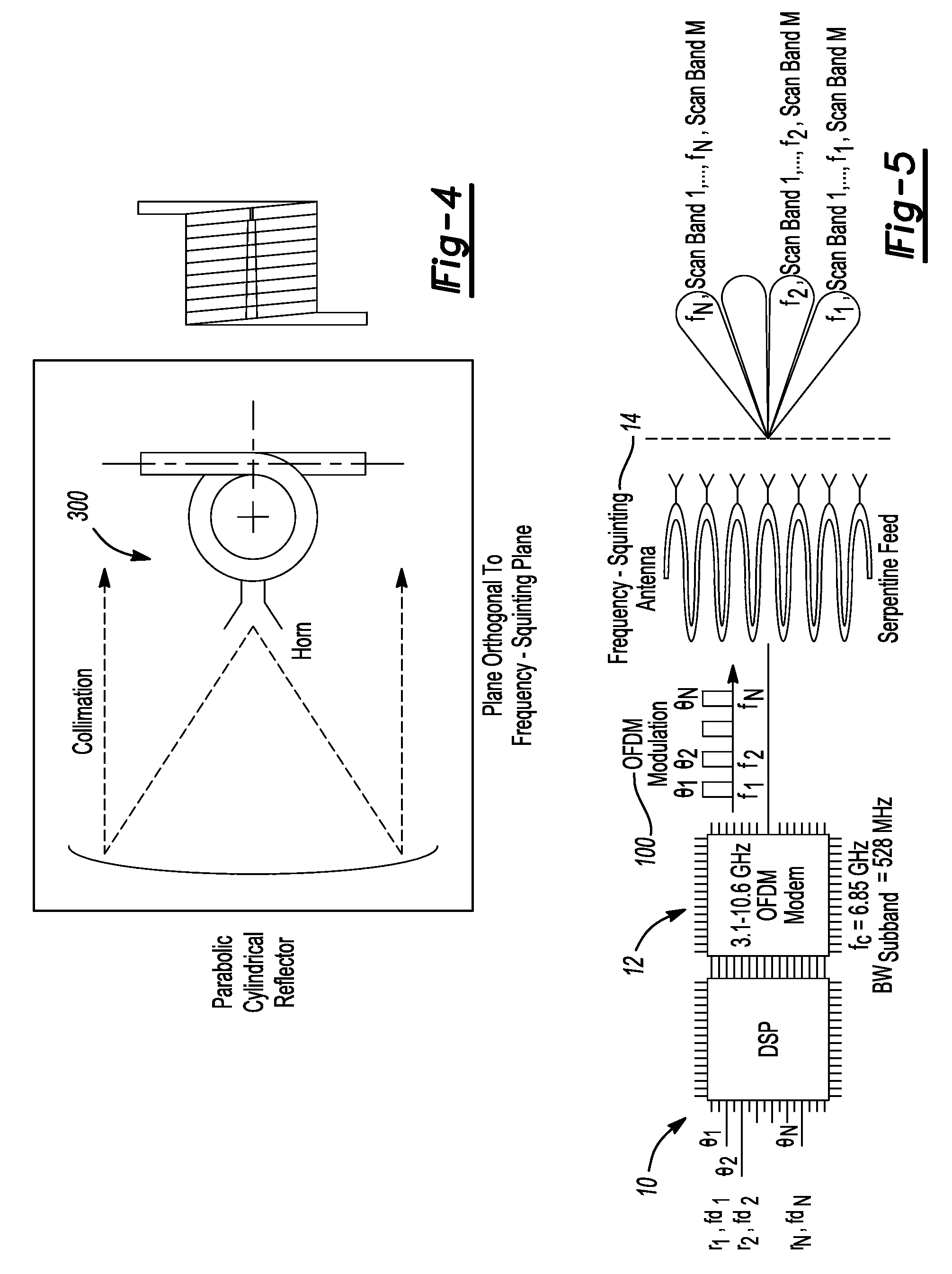
[0036]According to the principles of the present teachings, a radar system 10 is provided having an orthogonal frequency division multiplexing (OFDM) modem 12 and a frequency scanning antenna 14 operably coupled to OFDM modem12, as illustrated in FIG. 1. The OFDM modem 12 outputs an OFDM modulation 100. The frequency scanning antenna 14 radiates radio frequency (RF) energy based on the OFDM modulation. Directionality of the frequency scanning radar 14 is de...


PUM


Abstract

A radar system is disclosed, which comprises an orthogonal frequency division multiplexing (OFDM) modem and a frequency scanning antenna. In transmit, the OFDM modem modulates radar waveforms and the frequency scanning antenna radiates the OFDM modulated radio frequency (RF) energy. In receive mode, the frequency scanning antenna captures the echoes and the OFDM modem demodulates the echoes. Directionality of the frequency scanning antenna is dependent upon RF carrier frequency. In other features, the radar system further comprises a transmit / receive (T / R) module that up-converts and amplifies the OFDM modulation, and outputs the amplified signal to the frequency scanning antenna. The T / R module amplifies and down-converts a received RF echo from the frequency scanning antenna and outputs the down-converted echo to the OFDM modem. A plurality of scanning angles are measured simultaneously.

Description

CROSS-REFERENCE TO RELATED APPLICATIONS[0001]This application claims the benefit of U.S. Provisional Application No. 60 / 974,144, filed on Sep. 21, 2007. The entire disclosure of the above application is incorporated herein by reference.FIELD[0002]The present disclosure relates to radar systems and, more particularly, relates to a phased array comprising an orthogonal frequency division multiplexing (OFDM) modem and a frequency scanning antenna to provide high-resolution millimeter-wave imaging through low-cost and low-profile angle detection.BACKGROUND AND SUMMARY[0003]This section provides background information related to the present disclosure which is not necessarily prior art. This section further provides a general summary of the disclosure, and is not a comprehensive disclosure of its full scope or all of its features.[0004]Radio detection and ranging (radar) is used to sense angle, range and velocity of (moving) scatterers in the environment. Radar sensor capabilities of mer...

Claims


Application Information

Patent Timeline
Patent Type & Authority Patents(United States)
IPC IPC(8): G01S13/00
CPCG01S7/03G01S13/32G01S13/536G01S13/584H01Q3/22H01Q25/00
Inventor VAN CAEKENBERGHE, KOENBRAKORA, KARLSARABANDI, KAMAL
Owner RGT UNIV OF MICHIGAN
Why Eureka
Try Eureka