
Method for performing adaptive variable waveform switching to track target

A tracking target and self-adaptive technology, applied in the direction of radio wave reflection/re-radiation, radio wave measurement system, use of re-radiation, etc. and other problems, to achieve the effect of continuous and stable tracking of the target, low interception performance, and low transmission power

Active Publication Date: 2017-09-01
LINGBAYI ELECTRONICS GRP
View PDF6 Cites 18 Cited by
  • Summary
  • Abstract
  • Description
  • Claims
  • Application Information

AI Technical Summary

Problems solved by technology

[0005] The purpose of the present invention is to provide a short echo receiving period, high resource utilization rate of scanning time, and the ability to increase the radar detection distance in view of the shortcomings of the conventional vacuum tube tracking radar antenna, such as large aperture, high transmission power, and poor interception performance. , The tracking target is continuous and stable, and the antenna aperture is small, the transmission power is low, and the interception performance is good, and the adaptive variable waveform switching method for tracking the target

Method used


Image

  • Method for performing adaptive variable waveform switching to track target
  • Method for performing adaptive variable waveform switching to track target
  • Method for performing adaptive variable waveform switching to track target

Examples


Embodiment Construction

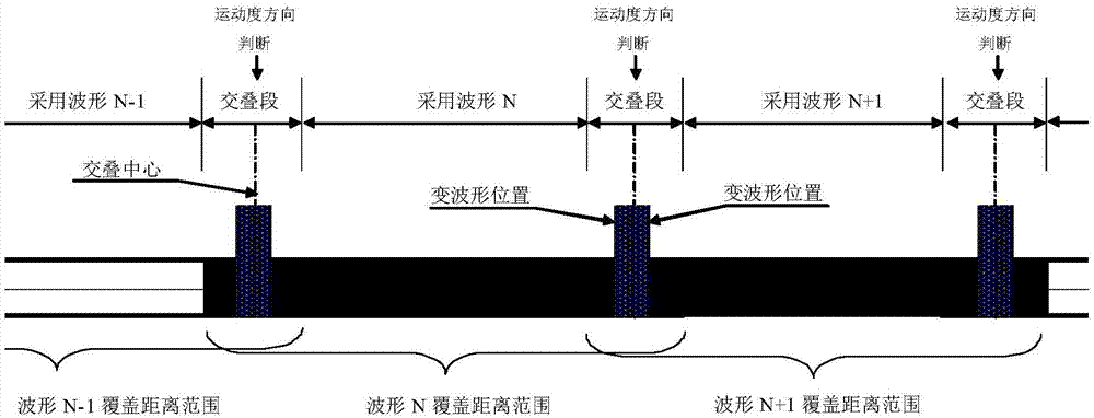
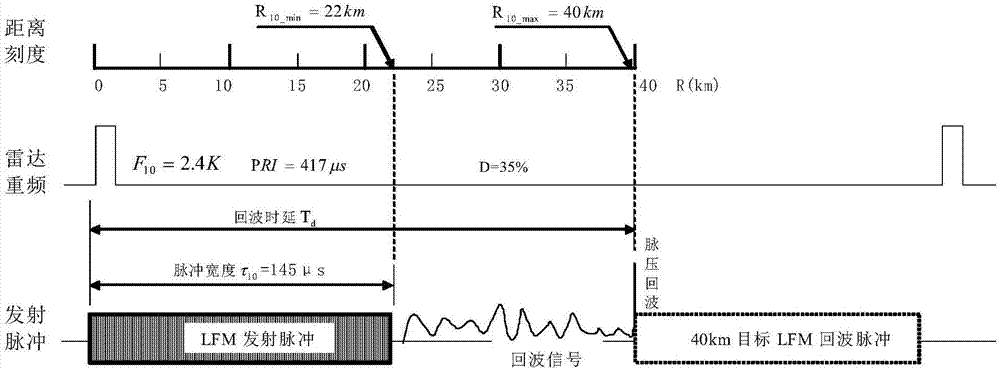
[0022] refer to Figure 1-3 . refer to Figure 1-3 . According to the present invention, according to the distance detection range R required by the radar and the allowable transmitter duty cycle D, the pulse width τ is calculated N and radar pulse repetition frequency F N ;According to the principle of radar, the detection range R required by the radar is divided into N sections, and the distance coverage of each section is R N_min ~R N_max , and the overlapping coverage of adjacent distance segments; then segment R according to the radar detection distance N , beam width θ, operating wavelength λ, radar repetition frequency F N , distance resolution unit △R, target velocity V and target acceleration a, calculate the maximum scan time T allowed for each segment N , to determine the coherent accumulated pulse number n and the required distance coverage R when the target flies from far to near or from near to far N As the target changes, the corresponding pulse width τ ...


PUM


Abstract

The present invention discloses a method for performing adaptive variable waveform switching to track a target. The invention aims to provide a target tracking method which is short in echo receiving period, high in scanning time resource utilization rate and is capable of increasing radar detection distances. The realization process of the method of the invention includes the following steps that: on the basis of a distance detection range R required by a radar and an allowable transmitter duty ratio D, the detection range R required by the radar is divided into N segments, and adjacent distance segments are overlapped; the allowable maximum scanning time of each segment is calculated according to the maximum distance, beam width, wavelength, target speed and target acceleration of each distance segment; a pulse width and a radar pulse repetition frequency corresponding to each segment are calculated; the allowable maximum scanning time of each segment is calculated; and phase-coherent accumulation pulse counts corresponding to each distance segment is determined according to the maximum scanning time, and radar waveform parameters according to which corresponding pulse widths and radar pulse repetition frequencies change correspondingly when required distance coverage changes with the target during a period when the target flies from the distant to the near or from the near to the distant are also determined.

Description

technical field [0001] The invention relates to a tracking method for a target tracking system adaptive variable waveform target, which can be widely used in the new development or reconstruction of single target tracking system radars such as meteorological radars, measurement radars and military radars. Background technique [0002] In recent years, the optimization of transmitting waveforms for target tracking has received extensive attention, among which how to adaptively select transmitting waveforms is one of the difficulties in its research. In the existing technology, a waveform adaptive selection module is added to the traditional radar target tracking system. Based on the Kalman filter and facing the single target background, the inverse of the Fisher information matrix in the parameter estimation theory is used as the observation noise covariance, and the transmitted waveform and The relationship between tracking and filtering, through waveform selection and param...

Claims


Application Information

Patent Timeline
IPC IPC(8): G01S13/72
CPCG01S13/723
Inventor 谭博陈娟张静王山川尹建军
Owner LINGBAYI ELECTRONICS GRP
Learn More