Integration of ex situ fabricated porous polymer monoliths into fluidic chips

a technology of porous polymer monoliths and fluidic chips, which is applied in the manufacture of electrode systems, electric discharge tubes/lamps, mechanical vibration separation, etc., can solve the problems of limited monolith potential in microfluidic applications, significant variability in uv dose, and poor control of the resolution of the resulting monoliths, etc., to achieve enhanced processing throughput

Active Publication Date: 2015-11-12
UNIV OF MARYLAND
View PDF3 Cites 54 Cited by
  • Summary
  • Abstract
  • Description
  • Claims
  • Application Information

AI Technical Summary

Benefits of technology

[0023]One aspect of the invention relates to incorporation of discrete high aspect ratio polymer monolith elements into thermoplastic fluidic chips. Some embodiments relate to methods for incorporation may be entirely different than conventional methods in that they involve ex situ fabrication of bare monolith elements followed by integration of the preformed monoliths into the final microfluidic system. In some embodiments, the ex situ fabricated bare monolith elements may also be functionalized ex situ. In some embodiments, the integration of the preformed bare monolith elements may be solvent-assisted integration. In some embodiments, the ex situ fabrication technique may allow for multiple monolith elements of differing chemistry, porosity, and / or functionality to be fabricated off-chip in a parallel batch process before integration of one or more discrete elements into the final device. In some embodiments, the ex situ approach may provide greatly enhanced processing throughput over in situ monolith preparation by eliminating the need for sequential processing steps to be performed on-chip for the preparation of single monolith zones. In some embodiments, the ex situ approach may allow multiple monoliths with different surface and bulk properties to be integrated within a single microfluidic chip using a unified fabrication process. Examples showing the utility of the ex situ integration method include fabrication of a multi-element immunosensor as well as a microfluidic wettability-based bubble separator composed of closely spaced hydrophobic and hydrophilic monoliths.

Problems solved by technology

However, in situ integration presents a number of challenges that limit the potential for monoliths in microfluidic applications.
For example, because the optical mask used during contact photolithography is necessarily displaced from the embedded microchannels by the thickness of the microfluidic cover plate, diffraction of light at the mask edges leads to significant variability in UV dose at the boundaries of the exposed region, resulting in poor control over the resolution of the resulting monoliths.
In addition, diffusive transport of prepolymer components during the phase separation and polymerization process results in poor monolith homogeneity at the UV-exposed boundary.
Another constraint that limits the potential of in situ fabricated porous monolith materials for microfluidic applications is that the in situ photopolymerization process requires a solution of monolith precursors, photoinitiators, and porogens to be injected into the microchannels prior to UV exposure, followed by extensive washing steps and any applicable functionalization operations needed to modify the monolith surface.
These steps can be cumbersome and highly time consuming, with a typical device requiring a sequence of 3 or more perfusion steps performed over a period of several days.
The incursion of precursor, wash, and functionalization solutions into other regions of the microfluidic system during the various perfusion steps can also affect the channel surface chemistry in unintended or undesirable ways.
In situ photopolymerization also necessitates the use of a UV-transparent chip material to allow for exposure through the top or bottom of the chip, limiting the range of substrate materials in which polymer monoliths can be fabricated in situ.
Additionally, the chip substrate must also be compatible with the solvent used to induce phase separation during polymerization, further limiting the substrate material options.
Another limitation of in situ fabricated monoliths relates to the attachment of the porous material to the microchannel walls.
However, despite the various attachment schemes, avoiding delamination remains a challenge for monoliths fabricated in situ in microchannels.
Because monoliths shrink in proportion to their size during polymerization, these attachment schemes become increasingly difficult in larger channels.
This phenomenon, combined with the spatial limitations of masked photoinitiation, means that well sealed in situ fabricated monoliths with high aspect ratio (hydrodynamic diameter to length) are exceedingly difficult to produce.
Moreover, the overall capillary integration process imposes a mismatch in cross-sectional dimensions between the channels in the PDMS chip and the capillary-supported monoliths, resulting in a dead volume at the fluidic interfaces between each capillary and the mating channel.
In addition, the technique relies on compliant elastomer channel walls for effective leak-free integration of the silica capillaries and, thus, cannot be readily adapted to thermoplastic microfluidic chips fabricated using traditional bonding strategies.
Nucleic acid capture and purification isolates the nucleic acids from other components of biological sample matrices, such as cell lysate and blood plasma, which could introduce components that inhibit PCR replication of target deoxyribonucleic acid (DNA) sequences, degrade the efficiency of the amplification process, and result in poor assay reproducibility.
While high loading levels and extraction efficiencies have been reported using chitosan as a charge-switching polymer for microfluidic DNA capture and release, known methods require long channels distributed over large device areas to achieve this performance.
While high aspect ratio microstructures can be used to enhance surface area, this approach requires the application of complex fabrication methods that are undesirable for use in disposable sample preparation chips.
However, due to the limited reaction efficiency, this technique required a 6 day, room temperature perfusion of protein solution at pH 8 through the GMA monolith to achieve adequate conjugation.
For conventional microfluidic applications, where monoliths are fabricated in situ within a microchannel by patterned photopolymerization, the extended reaction time renders the direct reaction route impractical, since each individual chip requires photolithographic fabrication of the monolith elements followed by extended reagent perfusion and incubation.

Method used


Image

  • Integration of ex situ fabricated porous polymer monoliths into fluidic chips
  • Integration of ex situ fabricated porous polymer monoliths into fluidic chips
  • Integration of ex situ fabricated porous polymer monoliths into fluidic chips

Examples


Embodiment Construction

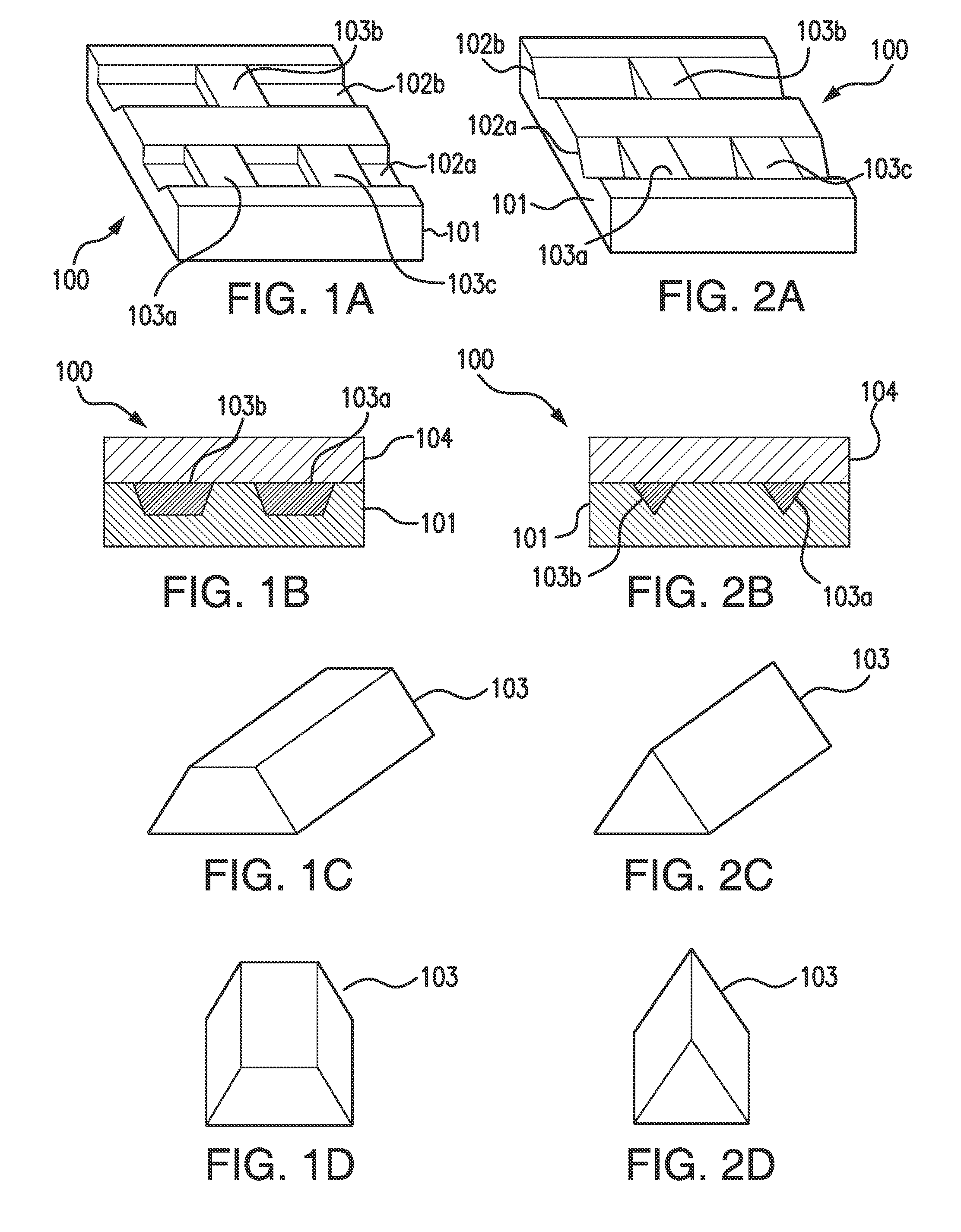
[0075]FIG. 1A illustrates a perspective view of top, side, and end of a portion of a channel substrate 101 of a fluidic chip 100 embodying aspects of the present invention. In some non-limiting embodiments, the fluidic chip 100 may be a microfluidic chip. In some embodiments, the fluidic chip 100 may include a channel substrate 101. In some non-limiting embodiments, the channel substrate 101 may comprise a thermoplastic, such as, for example and without limitation, cyclic olefin copolymer (COC). In some embodiments, the channel substrate 101 may include one or more channels 102. In some non-limiting embodiments, the one or more channels 102 may comprise one or more microchannels. In some non-limiting embodiments, as illustrated in FIG. 1A, the one or more channels 102 of the channel substrate 101 may include a first channel 102a and a second channel 102b.

[0076]In some non-limiting embodiments, the one or more channels 102 may have a width within a range greater than or equal to 10 ...


PUM

PropertyMeasurementUnit
heightaaaaaaaaaa
heightaaaaaaaaaa
heightaaaaaaaaaa

Abstract

Bare porous polymer monoliths, fluidic chips, methods of incorporating bare porous polymer monoliths into fluidic chips, and methods for functionalizing bare porous polymer monoliths are described. Bare porous polymer monoliths may be fabricated ex situ in a mold. The bare porous polymer monoliths may also be functionalized ex situ. Incorporating the bare preformed porous polymer monoliths into the fluidic chips may include inserting the monoliths into channels of channel substrates of the fluidic chips. Incorporating the bare preformed porous polymer monoliths into the fluidic chips may include bonding a capping layer to the channel substrate. The bare porous polymer monoliths may be mechanically anchored to channel walls and to the capping layer. The bare porous polymer monoliths may be functionalized by ex situ immobilization of capture probes on the monoliths. The monoliths may be functionalized by direct attachment of chitosan.

Description

CROSS REFERENCE TO RELATED APPLICATIONS[0001]This application claims the benefit of priority to U.S. Provisional Application Ser. Nos. 61 / 971,107 and 61 / 971,091, filed on Mar. 27, 2014, which are incorporated herein by reference in their entireties.GOVERNMENT LICENSE RIGHTS[0002]This invention was made with government support under Contract No. R01AI096215 awarded by the National Institute of Health and under Contract No. N660011014003 awarded by the Space and Naval Warfare Systems Command. The government has certain rights in the invention.BACKGROUND[0003]1. Field of Invention[0004]The present invention relates to fabrication of porous polymer monoliths and integration of one or more porous polymer monoliths into a fluidic chip. More specifically, embodiments of the present invention relate to ex situ fabrication of porous polymer monoliths and integration of one or more porous polymer monoliths into one or more channels of a channel substrate of a fluidic chip.[0005]2. Discussion ...

Claims


Application Information

Patent Timeline
Patent Type & Authority Applications(United States)
IPC IPC(8): B01L3/00C08J9/224C08J3/24
CPCB01L3/502C08J3/246B01L2300/16B01L2200/12C08J9/224C08J2207/00C08J9/286C08J9/36C08J2201/026C08J2205/022C08J2205/024C08J2333/10C08J2333/14C08J2335/02B01L3/5023B01L3/502707B01L3/502723B01L3/502753B01L2200/0631B01L2300/165C08F220/325C08F222/102C08F222/103B01J19/2485B01J2219/2402B01D2253/342B01J2219/2433B01J2220/82B01J20/3007B01J20/3242B01J20/3255
Inventor KENDALL, ERIC L.WEINHOLD, ERIKRAHMANIAN, OMIDDEVOE, DON L.
Owner UNIV OF MARYLAND
Why Eureka
Try Eureka