
Programmable load forming system, components thereof, and methods of use

a load forming system and forming system technology, applied in the direction of electric programme control, program control, instruments, etc., can solve the problems of time-consuming and inconvenient re-programming of the robot controller, not allowing the robot to be used for stacking bundles, and requiring robot down time, so as to improve process throughput, prevent misalignment during stacking, and easily alter the stacking pattern

Inactive Publication Date: 2011-08-16
ALLIANCE MACHINE SYST INTENAT
View PDF517 Cites 17 Cited by
  • Summary
  • Abstract
  • Description
  • Claims
  • Application Information

AI Technical Summary

Benefits of technology

"The invention is about a system and method for forming stacks of un-erected boxes using a robot and a computer. The system can download a calculated path for the robot to move the bundles of boxes to a predetermined position in a stacking pattern. The robot can also stop and rotate without interfering with other parts of the system. The system also includes a hopper for holding tie sheets and bottom sheets. The technical effects of the invention include improved process throughput, prevention of misalignment, and ease of use for operators."

Problems solved by technology

The re-programming of the robot controller is time consuming and inconvenient.
It also requires down time for the robot, thus, not allowing the robot to be used for stacking bundles.
The bundles of un-erected boxes also tend to be inconsistent in height and shape.

Method used


Image

  • Programmable load forming system, components thereof, and methods of use
  • Programmable load forming system, components thereof, and methods of use
  • Programmable load forming system, components thereof, and methods of use

Examples


Embodiment Construction

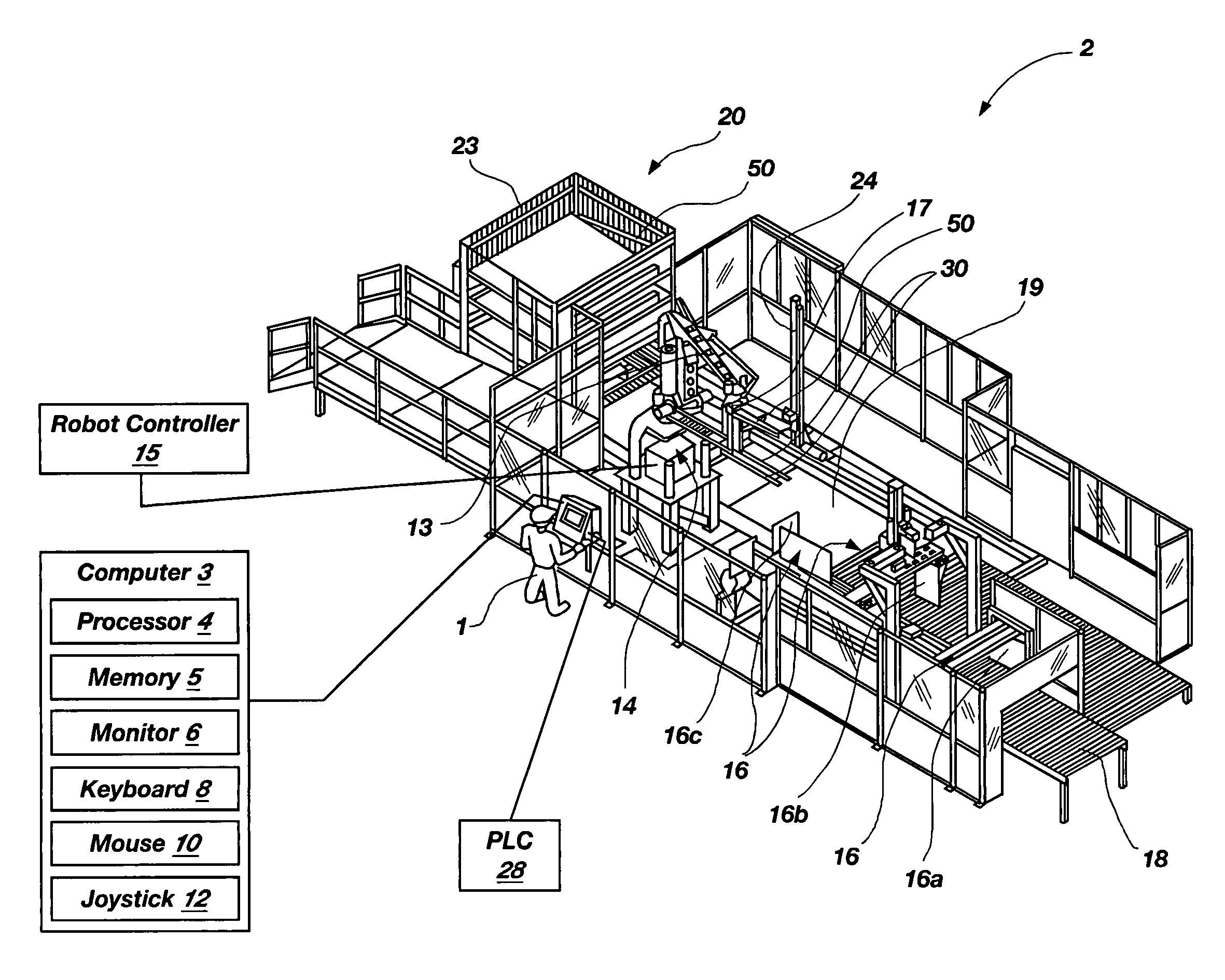
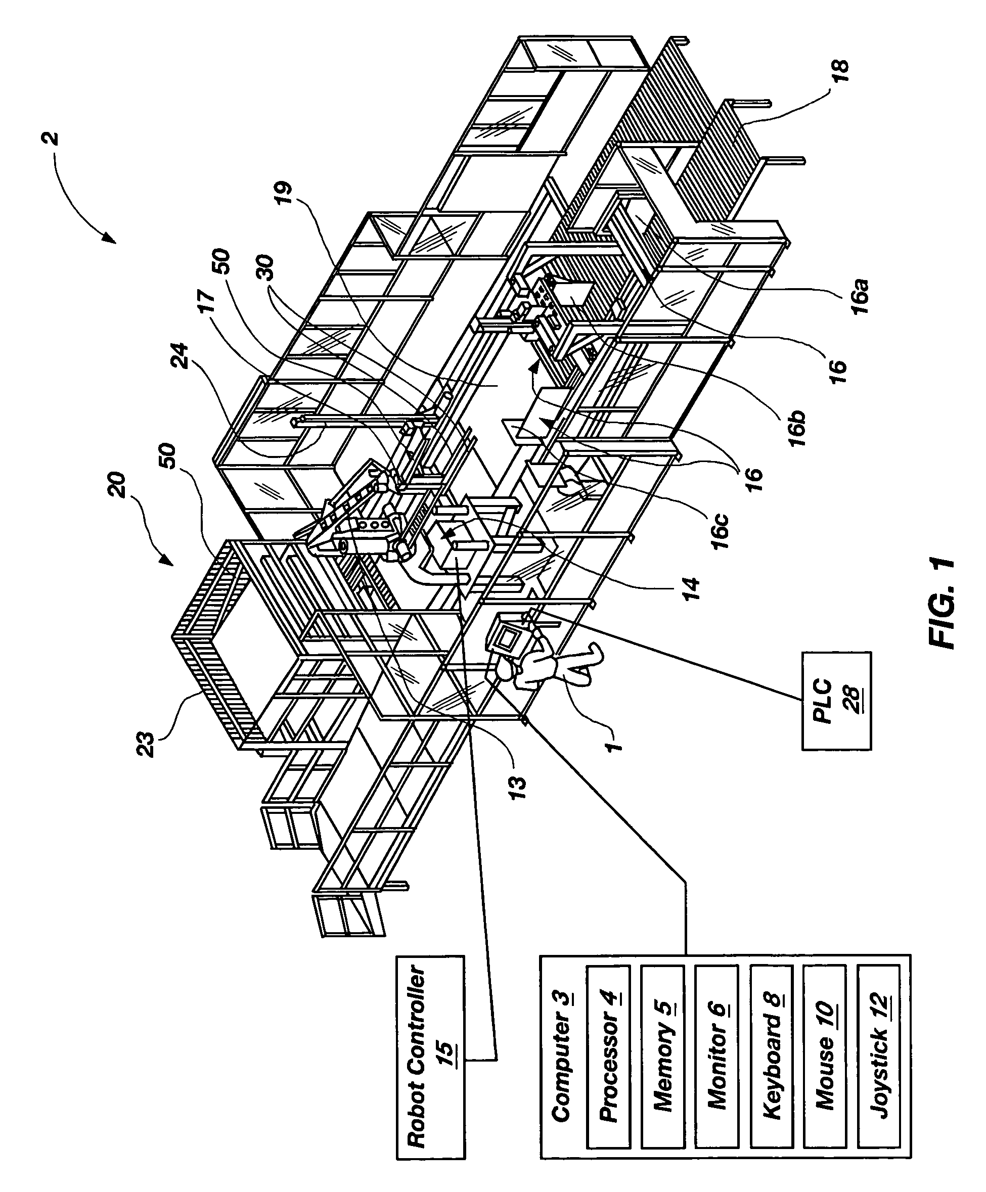
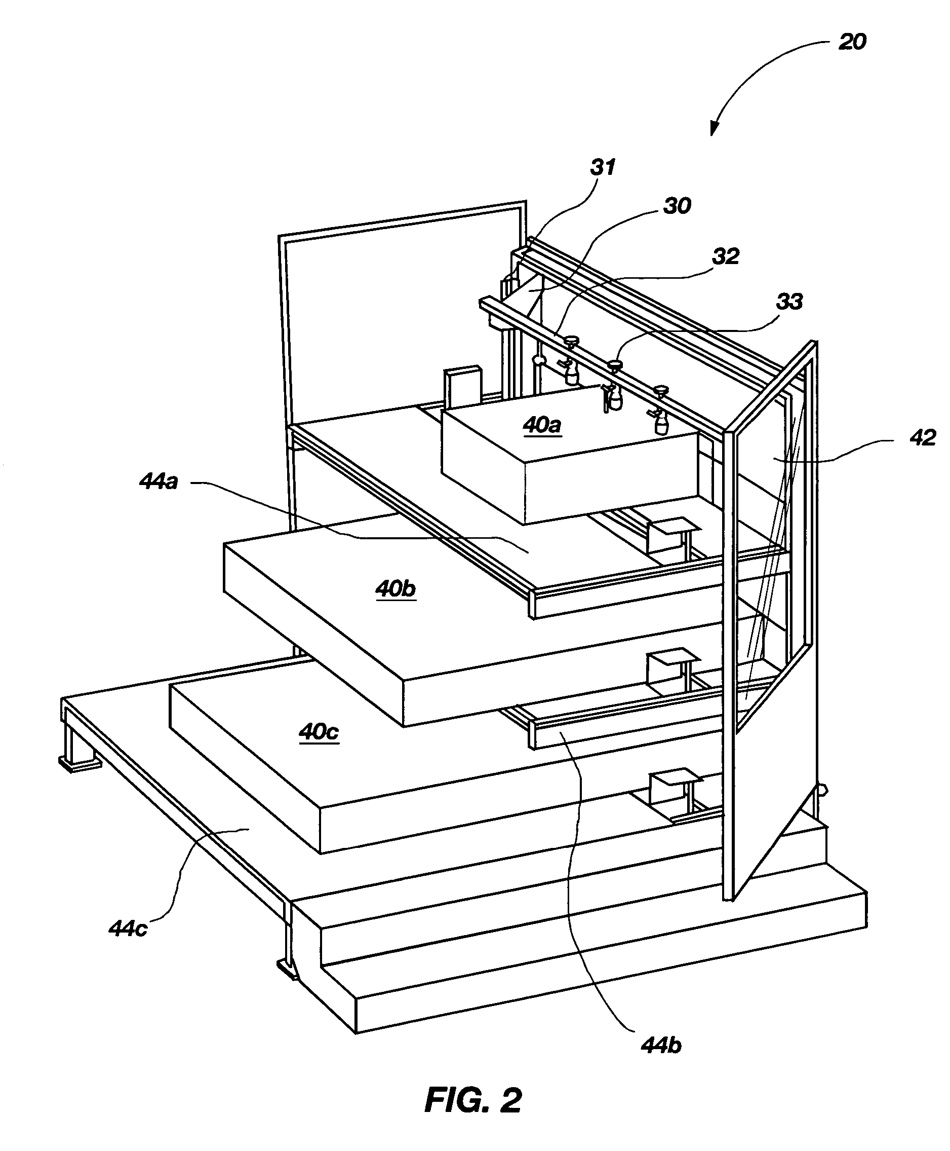
[0015]The invention is directed to programmable load forming systems, components thereof, and methods of using and controlling programmable load forming systems. The programmable load forming systems may be used for stacking bundles of un-erected boxes. The bundles may include boxes of un-erected, corrugated cardboard boxes that are strapped together or un-strapped. Many specific details of certain embodiments of the invention are set forth in the following description and FIGS. 1 through 5 in order to provide a thorough understanding of such embodiments. One skilled in the art, however, will understand that the invention may have additional embodiments, or that the invention may be practiced without several of the details described in the following description.

[0016]FIG. 1 shows a schematic isometric view of a programmable load forming system 2 according one embodiment of the invention. The programmable load forming system 2 is suitable for practicing various methods, which will be...


PUM

PropertyMeasurementUnit
interfaceaaaaaaaaaa
distanceaaaaaaaaaa
heightaaaaaaaaaa

Abstract

In one aspect, a programmable load forming system is programmed to perform the method of downloading a calculated path from the computer to the robot controller, moving one or more bundles along the calculated path to position the one or more bundles in a predetermined stacking position of a stacking pattern using the robot, and determining if the robot has completed moving along the calculated path. The calculated path is defined, in part, by the stacking pattern and other parameters such as, for example, bundle geometry, bundle levelness, bundle compressibility, among other parameters. In another aspect, the system is programmed to perform a method of sensing the top of a bundle and controllably placing a bundle. Additional aspects are directed to systems and methods of safely operating the robot and an inventive hopper design for holding bottom / tie sheets.

Description

CROSS-REFERENCE TO RELATED APPLICATIONS[0001]This application claims the benefit of Provisional Application No. 60 / 616,578, filed on Oct. 5, 2004, the disclosure of which is incorporated herein by reference.TECHNICAL FIELD[0002]The invention relates to programmable load forming systems, components thereof, and methods for stacking bundles of un-erected boxes.BACKGROUND OF THE INVENTION[0003]Load forming systems are commonly used to stack bundles of un-erected corrugated boxes. Load forming systems transport, using a conveyor, bundles of un-erected boxes. The bundles are then typically conditioned by a centering unit, a rotator, and / or a doubler. Pusher forks are used to transfer the bundle from the rotator to the pick-up location. A robot having a movable arm with a gripping mechanism is used to pick-up and move the bundles to a desired location on another conveyor unit. The robot stacks the bundles according to how the robot controller is programmed. Thus, the robot is programmed t...

Claims


Application Information

Patent Timeline
Patent Type & Authority Patents(United States)
IPC IPC(8): G06F19/00
CPCB65G61/00G05B2219/40006Y10T83/204Y10T83/2057Y10T83/2037
Inventor ALLEN, ROBERT M.BROWN, KEVIN P.HOLT, ANDREW B.VERSHUM, LYNN E.
Owner ALLIANCE MACHINE SYST INTENAT
Learn More