Data holding apparatus

a data holding and data technology, applied in the field of data holding apparatuses, can solve the problems of increasing the number of registers, the inability of conventional data holding apparatuses to use macroblock-adaptive frame/field coding, and the complexity of neighboring relationships, so as to reduce wasteful data transfer, reduce the increase in circuit size, and high speed

Inactive Publication Date: 2011-08-30
SOCIONEXT INC
View PDF9 Cites 0 Cited by
  • Summary
  • Abstract
  • Description
  • Claims
  • Application Information

AI Technical Summary

Benefits of technology

[0013]As shown in FIG. 2, in the conventional image coding (or decoding) processing, picture coding (or decoding) is basically performed on a macroblock basis. In recent years, the ISO / IEC Moving Picture Experts Group and the ITU-T Video Coding Experts Group have jointly made efforts to standardize MPEG-4 AVC and ITU H.264 as the next-generation image coding scheme with the goal of further enhancing image coding efficiency. One of the features of this new image coding technique is that the above-mentioned picture coding can be performed basically on a basis of a vertical pair of macroblocks as shown in FIG. 5. In such coding (or decoding) per macroblock pair, macroblocks are processed in the order of raster scanning in which a vertical transition within a pair of macroblocks is prioritized. In addition, if such coding per macroblock pair is employed, a frame structure and a field structure can be switched adaptively for each vertical pair of macroblocks in a picture. FIG. 6 shows one example where macroblock pairs of both the frame structure and the field structure are mixed in a picture. In FIG. 6, a vertically hatched region indicates a top macroblock in a macroblock pair of the field structure, namely a macroblock in a top field, while a horizontally hatched region indicates a bottom macroblock in a macroblock pair of the field structure, namely a macroblock in a bottom field. A vertically and horizontally hatched region indicates a macroblock pair of the frame structure.
[0043]Furthermore, it is possible to reduce the wasteful data transfer for the parameters common to a macroblock pair, and therefore speed up such data transfer.

Problems solved by technology

However, the conventional data holding apparatus cannot be used for the macroblock-adaptive frame / field coding (or decoding) in which the frame / field structures can be switched adaptively for each vertical pair of macroblocks.
In addition, if a data holding apparatus includes the same number of registers as that of the neighboring macroblocks as is the case with the conventional one, the problem is that not only the number of registers but also the circuit size of the apparatus increase.
Compared with the conventional coding, such macroblock-adaptive frame / field coding increases the number of reference macroblocks which have neighboring relationship with a current macroblock and whose parameters can be used for coding the current macroblock, and therefore renders the neighboring relationship more complicated.

Method used


Image

  • Data holding apparatus
  • Data holding apparatus
  • Data holding apparatus

Examples


first embodiment

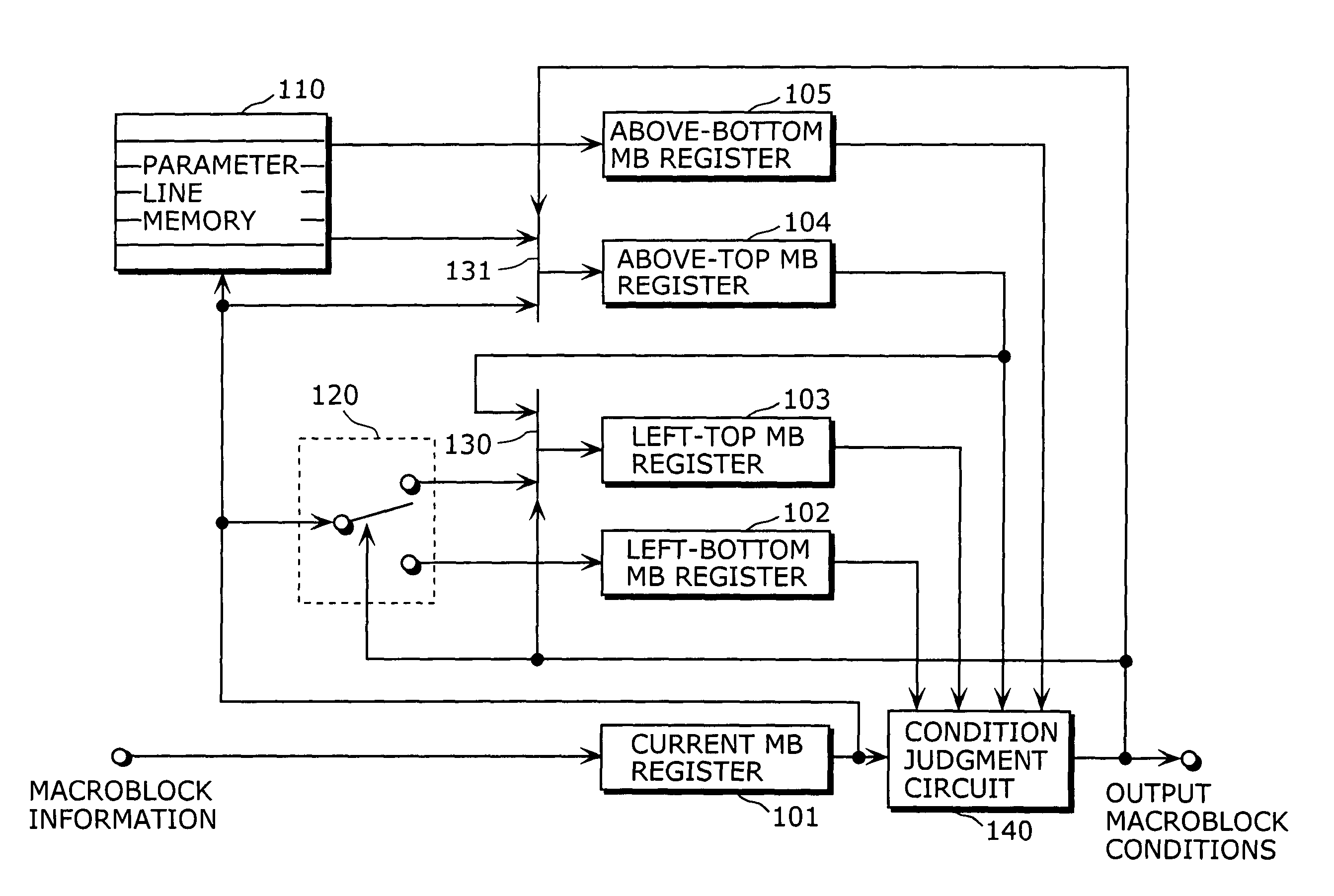
[0058]FIG. 9 is a diagram showing a structure of a data holding apparatus in the first embodiment of the present invention. This data holding apparatus includes a register 101 for a current macroblock (current MB register), a register 103 for a top macroblock in a left neighboring marcoblock pair (left-top MB register), a register 102 for a bottom macroblock in a left neighboring macroblock pair (left-bottom MB register), a parameter line memory 110, a register 104 for a top macroblock in an above neighboring macroblock pair (above-top MB register), a register 105 for a bottom macroblock in an above neighboring macroblock pair (above-bottom MB register), a distributor 120, a selector 130, a selector 131 and a condition judgment circuit 140. Description of each element is as follows.

[0059]The current MB register 101 holds coding (or decoding) parameter set for a current macroblock. Here, a parameter set indicates the conditions for coding or decoding a macroblock, such as a motion ve...

second embodiment

[0082]FIG. 10 is a diagram showing a data holding apparatus in the second embodiment of the present invention. The data holding apparatus shown in this diagram includes a current-top MB register A01, a current-bottom MB register A02, a neighboring-bottom MB register A03, a neighboring-top MB register A04, a parameter line memory A10, selectors A31 to A34, a condition judgment circuit A40 and a vertical / horizontal processing switching unit A50.

[0083]The current-top MB register A01 holds the parameter set of the top macroblock in a macroblock pair containing a current macroblock (hereinafter referred to as a current macroblock pair).

[0084]The current-bottom MB register A02 holds the parameter set of the bottom macroblock in a current macroblock pair.

[0085]The neighboring-bottom MB register A03 holds the parameter set of the bottom macroblock among the parameter sets in the macroblock pair selected by the selector A31.

[0086]The neighboring-top MB register A04 holds the parameter set of...

third embodiment

[0102]FIG. 12 is a diagram showing a structure of a data holding apparatus in the third embodiment of the present invention. This data holding apparatus includes: a register 901 for a current macroblock (current register 901) which holds the parameters specific to each of two macroblocsks in a macroblock pair; a register 902 for a current macroblock (current register 902) which holds the parameters common to both macroblocks in a macroblock pair; a switch 950; a register 904 for a top macroblock in a left neighboring macroblock pair (left-top MB register 904); a register 903 for a bottom macroblock in a left neighboring macroblock pair (left-bottom MB register 903); a parameter line memory 910; a register 905 for a top macroblock in an above neighboring macroblock pair (above-top MB register 905); a register 906 for a bottom macroblock in an above neighboring macroblock pair (above-bottom MB register 906); a switch 951; a distributor 920; a selector 930; a selector 931 and a conditi...


PUM


Abstract

A data holding apparatus of the present invention is a data holding apparatus a data holding apparatus used for image processing in which an image is coded or decoded, on a macroblock basis, based on a field structure or a frame structure selected on a macroblock pair basis. This data holding apparatus includes: a current register which holds a parameter set of a current macroblock to be coded or decoded; and registers which respectively hold parameter sets of macroblocks having neighboring relationships with a current macroblock, and at least one of the registers selectively holds, in sequence, parameter sets of respective different macroblocks having the neighboring relationships, one parameter set at a time.

Description

BACKGROUND OF THE INVENTION[0001](1) Field of the Invention[0002]The present invention relates to a data holding apparatus used for an image coding apparatus and an image decoding apparatus which respectively codes and decodes an image on a macroblock basis while switching a field structure and a frame structure adaptively on a macroblock pair basis.[0003](2) Description of the Related Art[0004]FIG. 1 is a block diagram showing a structure of a conventional data holding apparatus included in an image coding apparatus and an image decoding apparatus which are compliant with the MPEG-2 standard (see INTERNATIONAL STANDARD ISO / IEC 13818-2: 2000, “Information technology-Generic coding of moving pictures and associated audio information: Video”). In FIG. 1, the data holding apparatus includes registers 501 to 503, a parameter line memory 504 and a condition judgment circuit 505.[0005]The register 501 holds a parameter set of a current macroblock to be coded or decoded (hereinafter referr...

Claims


Application Information

Patent Timeline
Patent Type & Authority Patents(United States)
IPC IPC(8): H04B1/66H04N19/00H04N19/423
CPCH04N19/176H04N19/134H04N19/423H04N19/112H04N19/61
Inventor ESAKI, KOTARO
Owner SOCIONEXT INC
Why Eureka
Try Eureka