

Optical space transmission device including rotatable member
a technology of optical space and transmission device, which is applied in the direction of electromagnetic transmission, close-range type systems, television systems, etc., can solve the problems of high transmission speed, high transmission speed, and inability to properly transmit video signals, etc., and achieve efficient and proper performance
- Summary
- Abstract
- Description
- Claims
- Application Information
AI Technical Summary
Benefits of technology
Problems solved by technology
Method used
Image

Examples
example 1
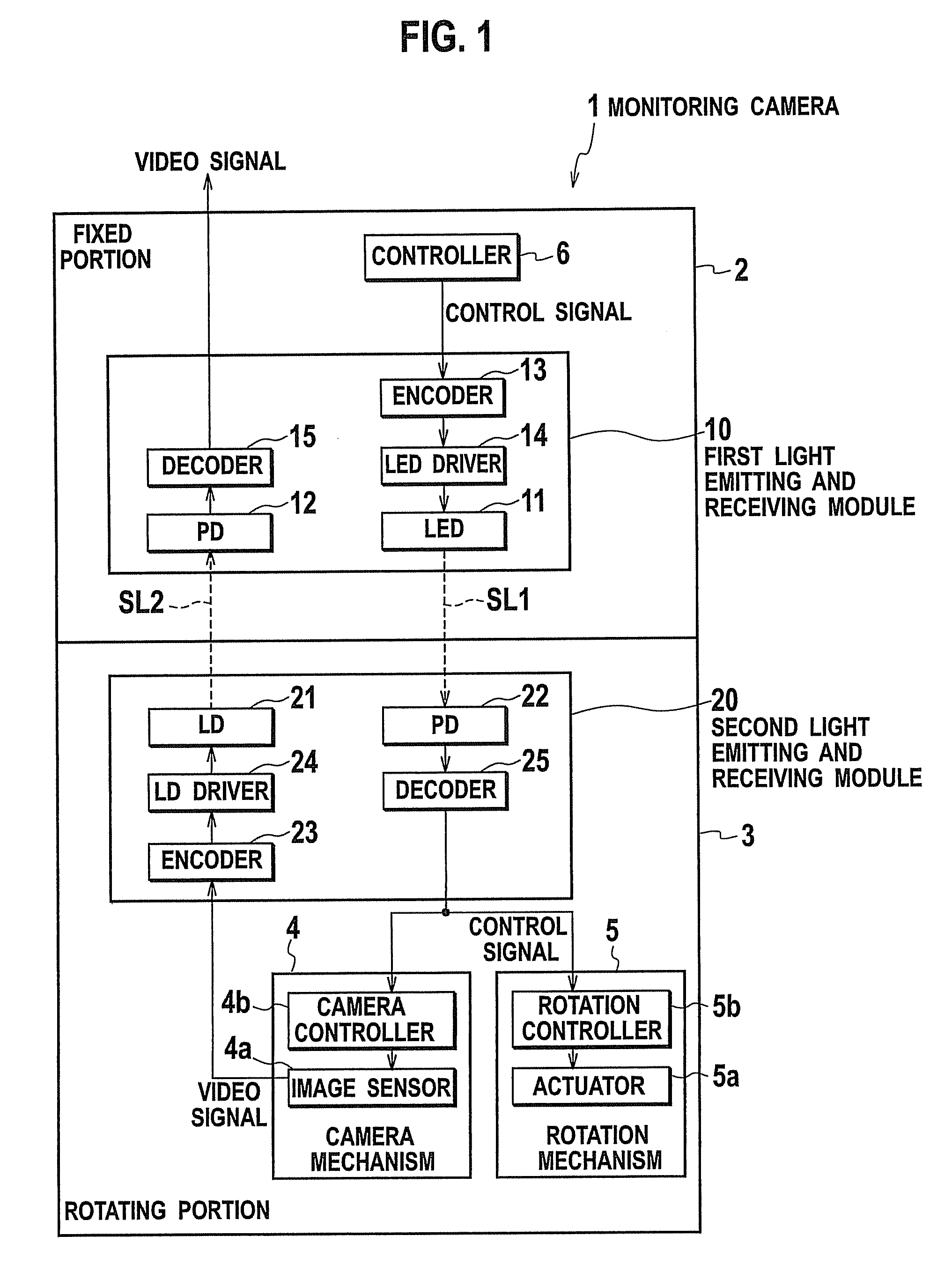
First Light Emitting and Receiving Module 10
[0036]LED 11; InGaAs LED
[0037]λ1; 980 nm
[0038]PD 12; GaAs PIN-type PD
(Second light emitting and receiving module 20)
[0039]LD 21; GaAs VCSEL (surface emitting laser diode)
[0040]λ1; 850 nm
[0041]PD 22; Si PD
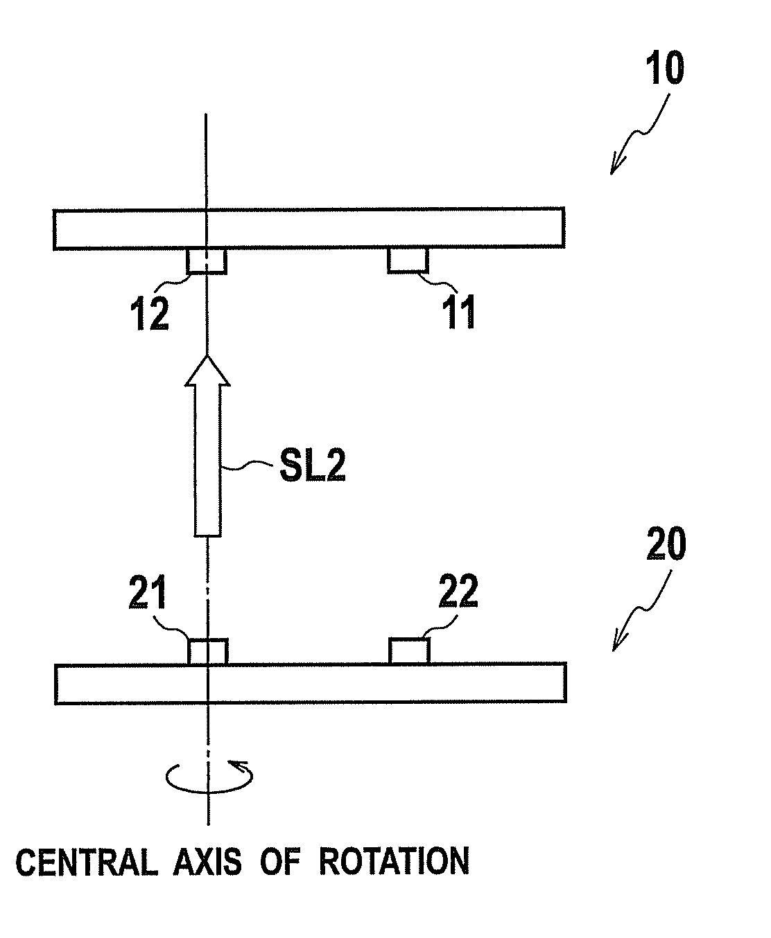
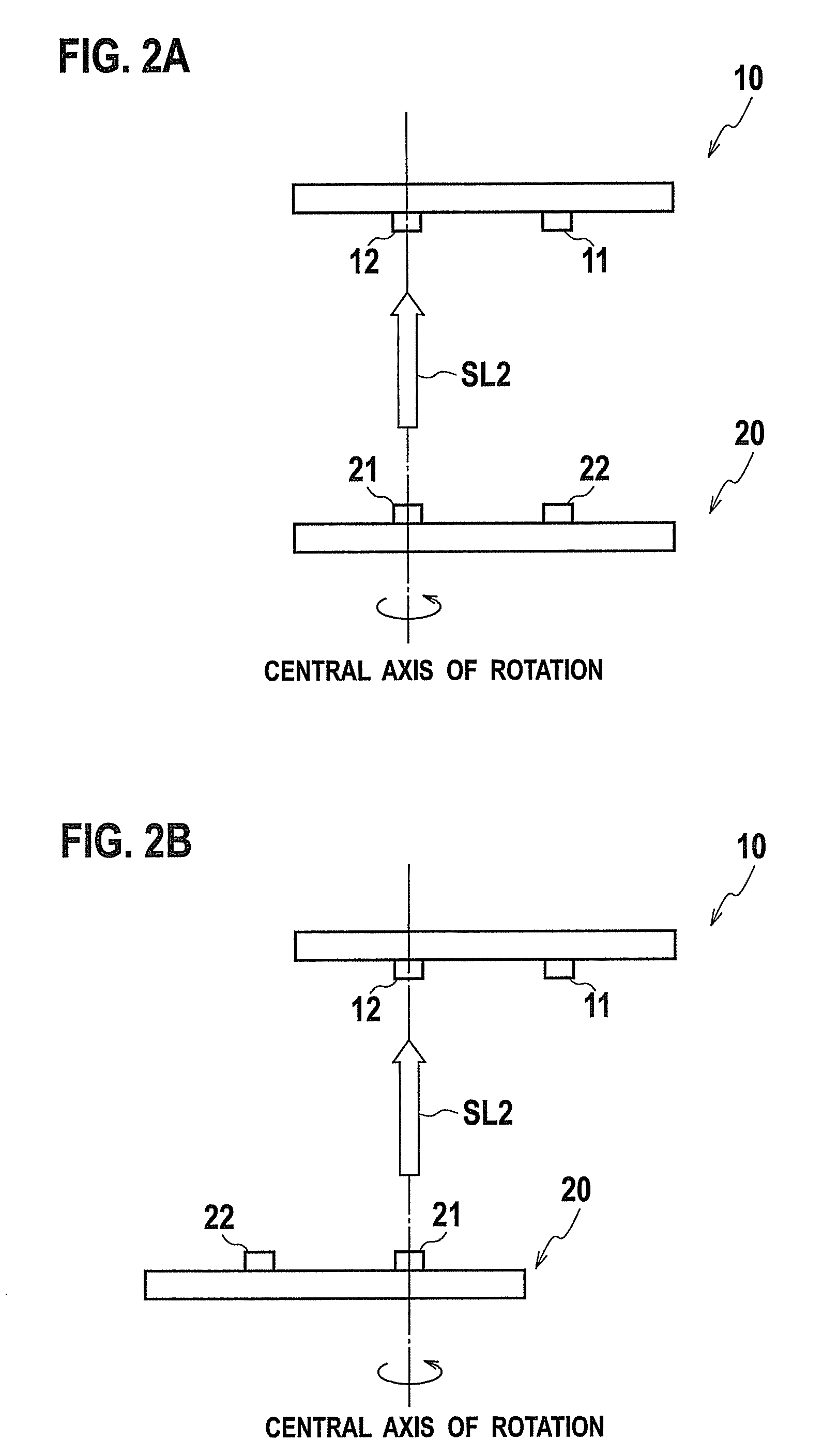
(Positional Relation)
[0042]LD 21 and PD 12 were arranged on the central axis of rotation.
[0043]Inter-module distance D; 20 mm
[0044]Inter-element distance L; 17.3 mm
[0045]Emission angle α of LED 11; 60°
(Countermeasure for Optical Crosstalk)
[0046]The material GaAs of the PD 12 has low enough sensitivity to wavelength of 980 nm. Resin mixed with dye having a cutoff wavelength of about 900 nm was applied to the PD 22 since the material Si of the PD 22 was sensitive to wavelength of 850 nm.
example 2
First Light Emitting and Receiving Module 10
[0047]LED 11; GaAs LED
[0048]λ1; 850 nm
[0049]PD 12; Si PD
(Second light emitting and receiving module 20)
[0050]LD 21; InGaAs VCSEL (surface emitting laser diode)
[0051]λ1; 980 nm
[0052]PD 22; GaAs PIN-type PD
(Positional Relation)
[0053]LD 21 and PD 12 were arranged on the central axis of rotation.
[0054]Inter-module distance D; 20 mm
[0055]Inter-element distance L; 17.3 mm
[0056]Emission angle α of LED 11; 60°
(Countermeasure for Optical Crosstalk)
[0057]The material GaAs of the PD 22 has low enough sensitivity to wavelength of 980 nm. Resin mixed with dye having a cutoff wavelength of about 900=m was applied to the PD 12 since the material Si of the PD 12 was sensitive to wavelength of 850 nm.
[0058]The optical space transmission device of the embodiment can be implemented by the structures shown in the above examples.
[0059]Hereinabove, as described in detail with the complete examples, according to the optical space transmission device of the embod...
PUM
 Abstract
Description
Claims
Application Information