Rotatable reflector support system

a support system and reflector technology, applied in the field of rotating reflector support system, can solve the problems of only being able to support the reflector on the side end wall, and the inability to remove the lamp from the lamp-holder

Inactive Publication Date: 2011-09-13
RETROFIT OOD
View PDF18 Cites 14 Cited by
  • Summary
  • Abstract
  • Description
  • Claims
  • Application Information

AI Technical Summary

Problems solved by technology

In certain previous patents, the support of reflectors on the fluorescent lamp results in the inability to remove the lamp from its lamp-holders, without also removing the reflector at the same time.
Furthermore, there are laboratories of compliance control with International and National Standards such as UL of USA that do not accept the reflector kit to be supported or fixed onto a fluorescent lamp.
Supporting the reflector on side end walls are only feasible on originally manufactured luminaries that bear a proper formation on their side end walls.
This is because the addition of side accessories for a reflector support, on already installed luminaries, obstructs the insertion and removal of at lamp from its lampholders or forces the lamp to be removed from the luminary along with the reflector.

Method used


Image

  • Rotatable reflector support system
  • Rotatable reflector support system
  • Rotatable reflector support system

Examples


Embodiment Construction

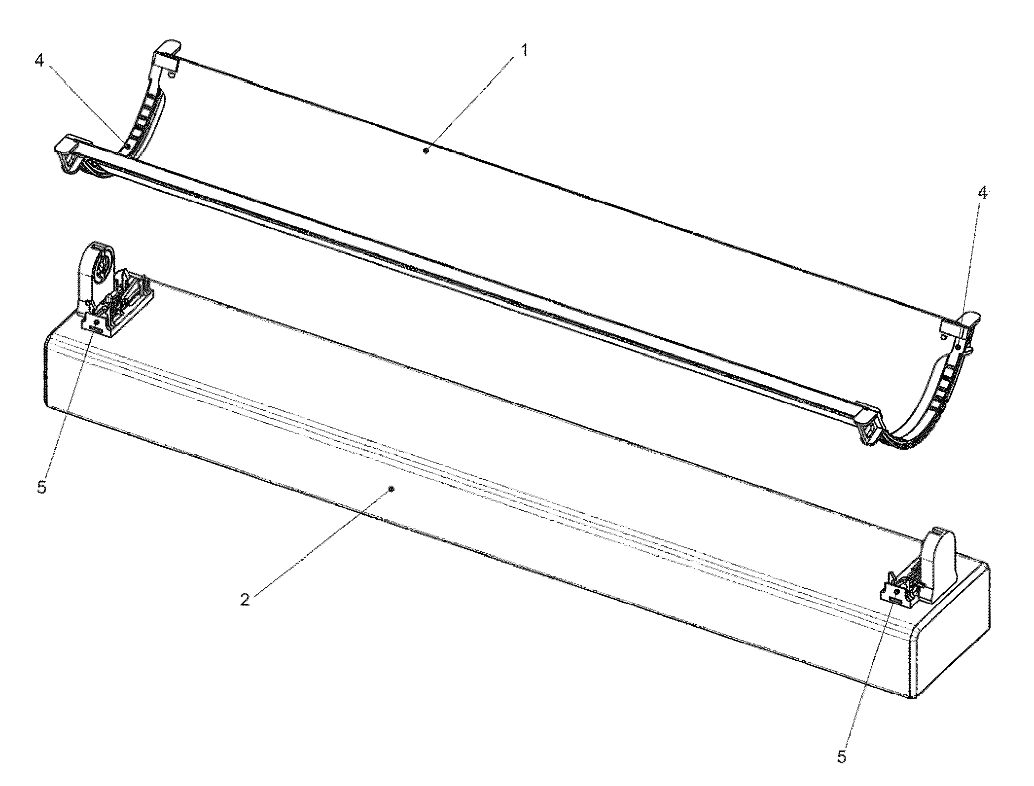
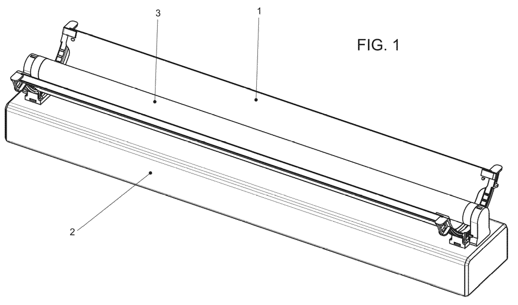
[0017]FIG. 1 shows the reflector 1 fitted onto the luminary 2 body behind the fluorescent lamp 3, with the aid of its support and rotation system. Reflector 1 is preferably of integrated parabolic shape.

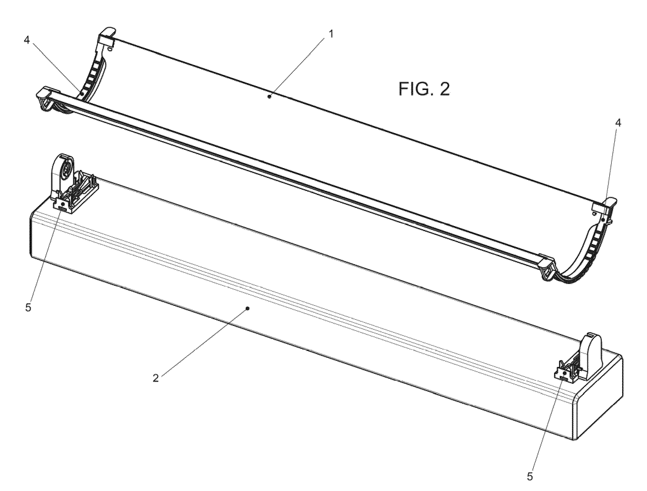
[0018]As it appears in FIG. 2, the reflector 1 is designed to be mounted onto the luminary 2 body through arch-shaped fittings 4 at each end of the reflector and associated reflector bases 5 that are respectively fixed onto each end of the luminary body.

[0019]FIG. 3 shows first and second flexible shanks 6a and 6b, as well as third and fourth flexible shanks 7a and 7b of each base. FIG. 4 shows a detail of first and second shanks 6a, 6b. The third and fourth flexible shanks 7a, 7b preferably have the same construction of shanks 6a, 6b, so that a separate description of shanks 7a, 7b is unnecessary.

[0020]Referring to FIG. 4, the first and second flexible shanks 6a, 6b have respective inclined surfaces 6c facing each other along the longitudinal axis of the luminary body, so as to guid...


PUM


Abstract

Disclosed is a system for the support and rotation of a reflector onto a body of a fluorescent luminary. The luminary body has first and second longitudinal ends along an axis. The rotatable reflector support system comprises an elongated reflector having first and second longitudinal ends. The reflector has first and second arch-shaped fittings proximate to the first and second reflector ends, respectively. First and second bases are mounted on the luminary body and are proximate to the first and second ends of the body, respectively. The side of each base faces the lamp, when the lamp is mounted in the luminary, and is shaped to engage a plurality of serial portions of an associated arch-shaped fitting in a manner allowing serial portions of the fitting, when manipulated, to slide along an arch-shaped path transverse to said axis and to hold the fitting in place when the fitting is not manipulated.

Description

FIELD OF THE INVENTION[0001]This invention is related to a reflector fixation or support system on bodies of fluorescent luminaries even when such luminaries are already installed. More specifically, such a system of reflector fixation provides the ability of reflector's rotation as well as the securing of the reflector in various positions of rotation.BACKGROUND OF THE INVENTION[0002]The reflectors of the prior art, which are mounted onto the fluorescent luminaries and have the ability, to rotate along the longitudinal axis of a fluorescent lamp, have, as means of support either the lamp itself or some other part, such as the side-walls of the luminary which are properly shaped.[0003]The reflector's fixation on the fluorescent lamp requires the existence of transverse louvers on the reflector's body by which the reflector is fixed on the lamp.[0004]In certain previous patents, the support of reflectors on the fluorescent lamp results in the inability to remove the lamp from its lam...

Claims


Application Information

Patent Timeline
Patent Type & Authority Patents(United States)
IPC IPC(8): F21V17/02
CPCF21V7/005F21V14/04F21V17/12F21Y2103/00
Inventor PARAVANTSOS, ANTONISPIPERIDIS, STAVROS
Owner RETROFIT OOD
Why Eureka
Try Eureka