Cord securing cover for an electrical outlet

a technology for electrical outlets and cords, applied in the direction of coupling parts engagement/disengagement, coupling device connection, incorrect coupling prevention, etc., can solve the problems of frequent disconnection of power to electrically powered devices, electrical plugs that do not fit tightly, and cords that can become electrically disconnected from the receptacle, so as to prevent unintentional disconnection of electrical plugs, restrict tension forces, and prevent unintentional disconnection of electrical cords

Active Publication Date: 2011-09-20
STAYCONNECT
View PDF33 Cites 19 Cited by
  • Summary
  • Abstract
  • Description
  • Claims
  • Application Information

AI Technical Summary

Benefits of technology

[0014]The present invention is an outlet cover for an electrical outlet which prevents unintentional disconnection of an electrical plug of an electrical cord from the electrical outlet. The outlet cover includes a plate having at least one opening sized and positioned to receive the electrical plug and a lid hingedly attached to the plate so that the lid can be moved between an open position that allows access to the electrical outlet and a closed position wherein the electrical outlet is covered by the lid. The lid includes a base having an outward facing surface, a prong having a proximal portion connected to, and extending outwardly from, the base, and a distal portion that is spaced from the base by the proximal portion, and at least one bump extending outwardly from the outward facing surface of the base. The electrical cord is positioned between the prong and the base, and also between the prong and the at least one bump such that the electrical cord engages the prong and the at least one bump. Accordingly, the prong and the at least one bump cooperate together to secure the electrical cord such that the electrical plug is not unintentionally disconnected from an electrical outlet when tension forces are applied to the electrical cord. In more preferred embodiments, the at least one bump includes first and second bumps, which are on opposed sides of the prong. Additionally, the prong and bumps are elongate, about the same in length, and have longitudinal axes that are generally parallel with each other. By having the electrical cord being engaged between the prong and bumps, tension forces applied to the cord are resisted by the prong and bumps so that the forces do not cause the cord to become unintentionally disconnected from the outlet.
[0015]The present invention also includes a method of securing an electrical cord to prevent unintentional disconnection of the electrical cord from an electrical outlet. The method includes the steps of providing an outlet cover. The outlet cover includes a plate having at least one opening sized and positioned to receive the electrical plug, a lid hingedly attached to the plate wherein the lid includes a base having an outward facing surface, a base having an outward facing surface, a prong having a proximal portion connected to, and extending outwardly from, the base, and a distal portion that is spaced from the base by the proximal portion, and at least one bump extending outwardly from the outward facing surface of the base. The method further includes the steps of moving the lid to an open position that allow for access to the electrical outlet; inserting the electrical cord through the at least one opening; plugging the electrical cord to the electrical outlet; positioning the electrical cord between the prong and the base; positioning the electrical cord between the prong and the at least one bump whereby the electrical cord is engaged against the prong and the at least one bump; applying a tension force to the electrical cord; and restricting movement of the electrical cord by engaging the electrical cord against the prong and at least one bump such that the electrical cord does not become disengaged from the electrical outlet. More preferably, the method further includes the steps of positioning the electrical cord over the first and second bumps and below the distal end of the prong, and restricting tension forces applied to the electrical cord from being transmitted to the electrical plug.

Problems solved by technology

Other related problems are that electrical plugs occasionally do not fit tightly into electrical outlet receptacles or the prongs become bent, causing frequent disengagement of power to electrically powered devices when the plug loosens from the outlet.
Further problematic with loose fitting plugs, particularly where the cord is lengthy or an extension cord is being used, is that the cord can become electrically disconnected from the receptacle simply by the weight of the cord.
Numerous power cord retaining devices have been configured in an attempt to solve the aforementioned problems, but all are not without problems of their own.
For example, some power cord retaining devices are large and bulky, creating an obstacle that persons, particularly children, could inadvertently engage when passing or playing near such devices.
And, of course, bulky retaining devices are generally unaesthetic, without designer form or style, and thus often not desirable for in-home use.
Another problem is that electrical outlets are oftentimes locate behind furniture or appliances and, in such cases, bulky power cord securing devices may also interfere with placement of furniture and appliances.
Additionally, many known cord securing devices have complex attachment mechanisms which are not well suited for quick and easy attachment and removal of a power cord, particularly when accessibility to the device is limited, for example when located behind furniture, or when an adult has limited dexterity.
A further problem is that some cord securing devices have a complex configuration which increases the cost of the devices and / or have removable parts which could inadvertently become lost rendering such devices useless.
Furthermore, many known cord securing devices are not weatherproof and, therefore, their use is restricted to the interior of a building, leaving unresolved the ability to secure power cords to outdoor electrical outlets.

Method used


Image

  • Cord securing cover for an electrical outlet
  • Cord securing cover for an electrical outlet
  • Cord securing cover for an electrical outlet

Examples


Embodiment Construction

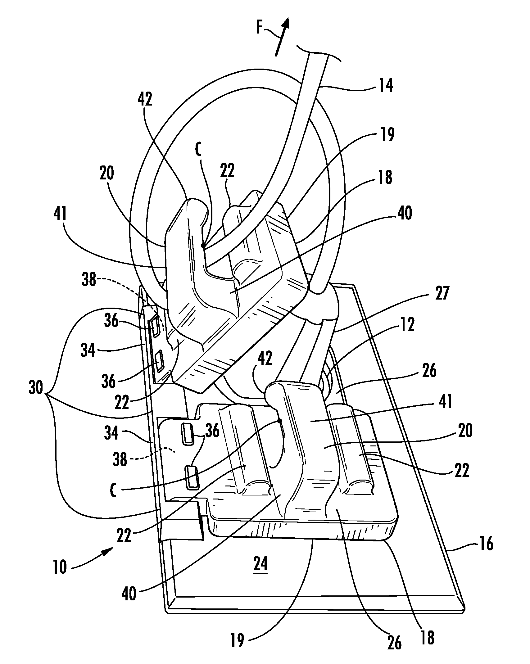
[0087]The present invention will now be described more fully hereinafter with reference to the accompanying drawings in which preferred embodiments of the invention are shown. This invention may, however, be embodied in many different forms and should not be considered as limited to the embodiments set forth herein. These exemplary embodiments are provided so that this disclosure will be both thorough and complete, and will fully convey the scope of the invention to those skilled in the art. Use of alpha-numeric reference numbers, in which the numeric portion is the same in different embodiments identifies that the element is functionally substantially similar in the various embodiments, whereas differences in the alpha portion identifies different embodiments. Accordingly, the description associated with a reference number, e.g. 20, is understood to be read into reference numbers with a different alpha portion, e.g. 20b, except as otherwise noted.

[0088]The present invention is an o...


PUM


Abstract

An outlet cover for an electrical outlet which prevents unintentional disconnection of an electrical plug of an electrical cord from the electrical outlet. The outlet cover includes a plate having at least one opening sized and positioned to receive the electrical plug and a lid hingedly attached to the plate so that the lid can be moved between an open position that allows access to the electrical outlet and a closed position wherein the electrical outlet is covered by the lid. The lid includes a base having an outward facing surface, a prong having a proximal portion connected to, and extending outwardly from, the base, and a distal portion that is spaced from the base by the proximal portion, and at least one bump extending outwardly from the outward facing surface of the base. The electrical cord is positioned between the prong and the base, and also between the prong and the at least one bump such that the electrical cord engages the prong and the at least one bump. Accordingly, the prong and the at least one bump cooperate together to secure the electrical cord such that the electrical plug is not unintentionally disconnected from an electrical outlet when tension forces are applied to the electrical cord.

Description

CROSS REFERENCE TO RELATED APPLICATIONS[0001]This application claims the benefit of U.S. Provisional Application No. 61 / 248,877, filed Oct. 5, 2009, which is incorporated herein in its entirety.BACKGROUND OF THE INVENTION[0002]1. Field of the Invention[0003]The present invention relates to the field of safety covers for electrical outlets and, more specifically, to an outlet cover for electrical outlets which prevents unintentional disconnection of an electrical plug from an electrical outlet.[0004]2. Description of the Related Art[0005]It is aggravating to the user of an electrical appliance, such as a vacuum cleaner, to have the power thereto be interrupted during use because the plug has either become loosened or dislodged from the outlet due to various tensions being placed on the power cord.[0006]Other related problems are that electrical plugs occasionally do not fit tightly into electrical outlet receptacles or the prongs become bent, causing frequent disengagement of power t...

Claims


Application Information

Patent Timeline
Patent Type & Authority Patents(United States)
IPC IPC(8): H01R13/62
CPCH01R13/6392
Inventor SCHUTTE, MICHAEL J.
Owner STAYCONNECT
Why Eureka
Try Eureka