Flow line connector assembly

a technology of connectors and connector assemblies, applied in the direction of couplings, sealing/packing, borehole/well accessories, etc., can solve the problems of environmental unacceptable, costly accidental disconnections,

Active Publication Date: 2018-03-22
SUS TECH GROUP
View PDF7 Cites 9 Cited by
  • Summary
  • Abstract
  • Description
  • Claims
  • Application Information

AI Technical Summary

Benefits of technology

[0024]The connector assembly optionally has a locked configuration, when the first and second parts are engaged, and the locking device is locked to resist movement of the restraining device. The connector assembly can also adopt an unlocked configuration. In the unlocked configuration, the locking device is de-activated, allowing deactivation of the restraining device. The arms are optionally biased gently outwards by a resilient device such as a spring, so when the locking device is disengaged, the dogs move out of the recesses, and the plug can be pulled out of the socket. The force of the...

Problems solved by technology

Accidental disconnections can be costly in terms of lost revenue from loss of valuable fluids and lost time taken to reconnect, and are ...

Method used


Image

  • Flow line connector assembly
  • Flow line connector assembly
  • Flow line connector assembly

Examples


Embodiment Construction

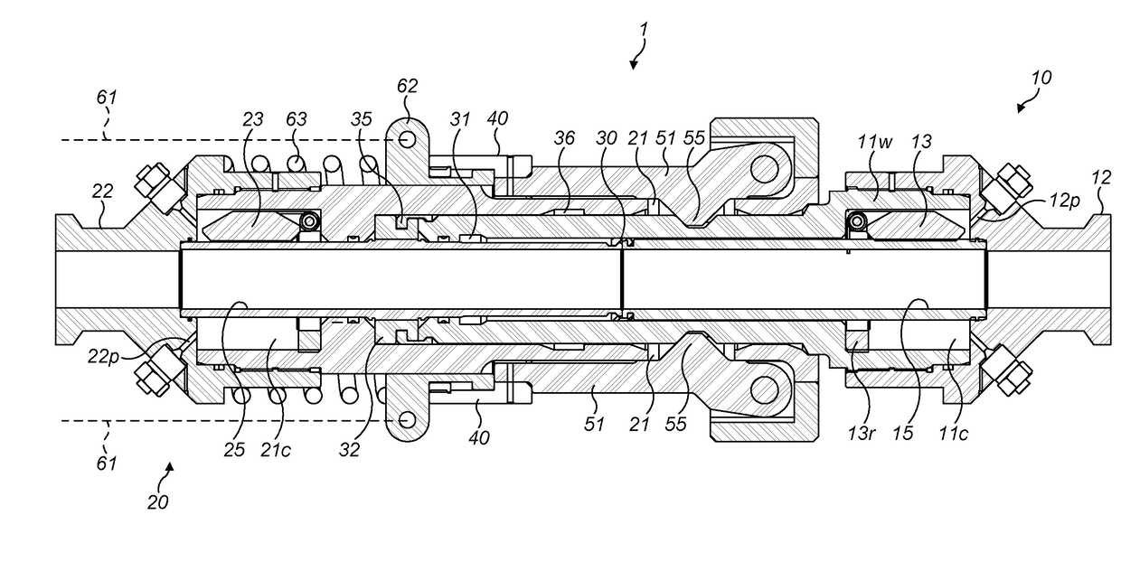
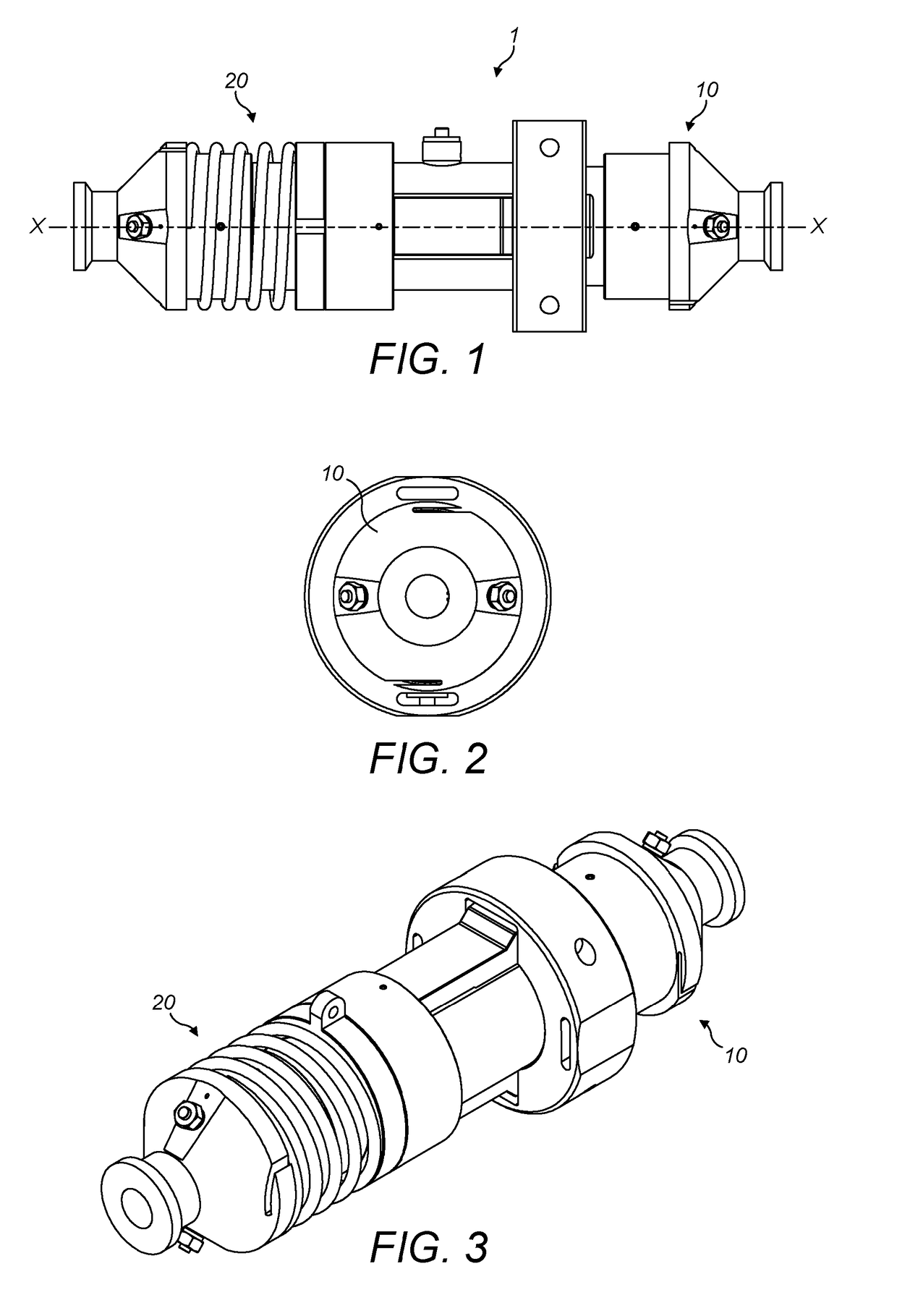
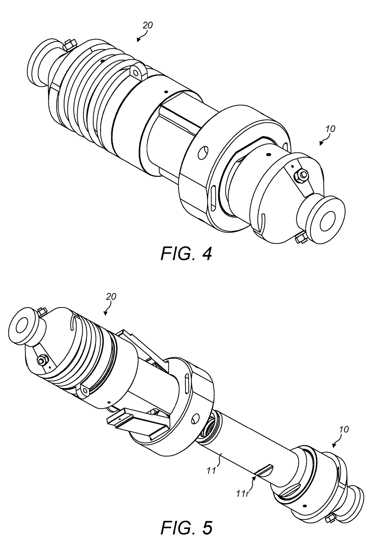
[0047]Referring now to the drawings, a connector assembly 1 comprises a first part 10 incorporating a plug 11 at its mating (outer) end for connection with a second part 20 incorporating a socket 21 at its mating end. The first part 10 has a cylindrical bore extending between opposite ends and aligned with the axis X-X of the connector assembly. The inner end of the first part 10 opposite the outer mating end with the plug 11 is adapted to connect to a flowline F configured to convey a fluid between a subsea well W and the surface supply ship V. The fluid can be supplied from the ship V to the well W or vice versa. The first part 10 is optionally connected to a well W, optionally to a wellhead stack S on the seabed, as shown in FIG. 11. The flowline has a clump weight CW to stabilise the flow line in the water column. Fluid supplied from the surface supply ship V is conveyed through the flowline F and through the connector 1. In this example, the connector assembly connects fluid co...


PUM


Abstract

A flow line connector assembly has first and second parts respectively comprising a plug, and a socket configured to receive the plug; a restraining device to resist disconnection of the first and second parts when the plug is received in the socket; and flow tubes, wherein each of the plug and the socket has a respective flow tube and the flow tubes are adapted to interconnect to form Ca conduit for fluid to flow between the first and second parts when the plug is received in the socket.

Description

[0001]This invention relates to a flow line connector assembly, and particularly to a flow line connector assembly in a subsea flow line used to convey a fluid to or from a subsea well.[0002]It is frequently necessary to convey fluid between a subsea well and the surface. When conveying fluid to the well, a flow line is normally deployed from a support vessel on the surface, or from a platform, to the seabed, and is optionally ballasted near the flow line terminal connector on the end of the flow line within reach of a well. The subsea stack on the seabed at the wellhead normally has a mating connector adapted to connect to the terminal connector in the end of the flow line in order to make up the connection.[0003]Changes in position of the vessel are minimised by dynamic positioning systems to avoid accidental disconnection of the flowline while fluids are flowing. Accidental disconnections can be costly in terms of lost revenue from loss of valuable fluids and lost time taken to r...

Claims


Application Information

Patent Timeline
IPC IPC(8): F16L37/32F16L37/096E21B17/046E21B33/038E21B43/013E21B34/06
CPCF16L37/32F16L37/096E21B17/046E21B33/038E21B43/013E21B34/06F16L55/07E21B2034/005E21B34/00E21B43/0107E21B43/0135F16L37/20F16L1/26F16L37/127F16L55/1015E21B2200/05E21B17/0465F16L37/00F16L55/1007E21B43/01
Inventor MCKAY, DAVID ERNEST
Owner SUS TECH GROUP
Why Eureka
Try Eureka