
Belt Buckle

Active Publication Date: 2015-12-03
RACER SPORTING GOODS
View PDF5 Cites 10 Cited by
  • Summary
  • Abstract
  • Description
  • Claims
  • Application Information

AI Technical Summary

Benefits of technology

The present invention is a belt buckle with a base and clamping plate for securely attaching a belt. It also has a frame and prong member for added strength. The buckle can be used with different types of belts and can save inventory and delivery costs. Additionally, it can be sold with a predetermined length of belt, making it easier for retailers to stock and sell.

Problems solved by technology

However, because the clamping plate simply engages the top wall of the belt, the belt can easily be forced by an external force to displace relative to the buckle base or to disconnect from the buckle base.
Further, if the belt is too thick or too thin, a different belt buckle may have to be used.
Further, conventional belt buckles cannot fit different belts of different materials perfectly.

Method used


Image

  • Belt Buckle
  • Belt Buckle
  • Belt Buckle

Examples


Embodiment Construction

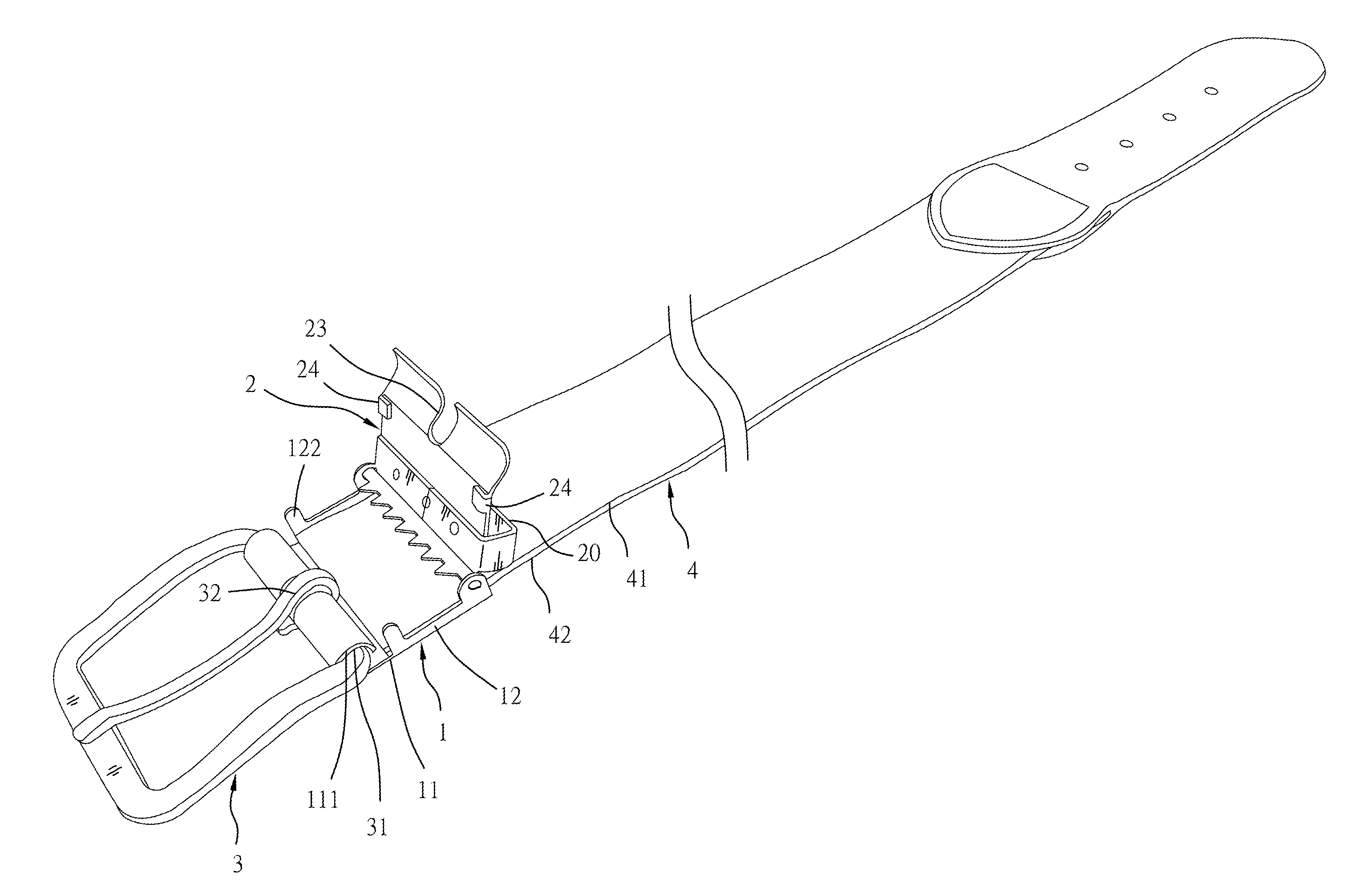
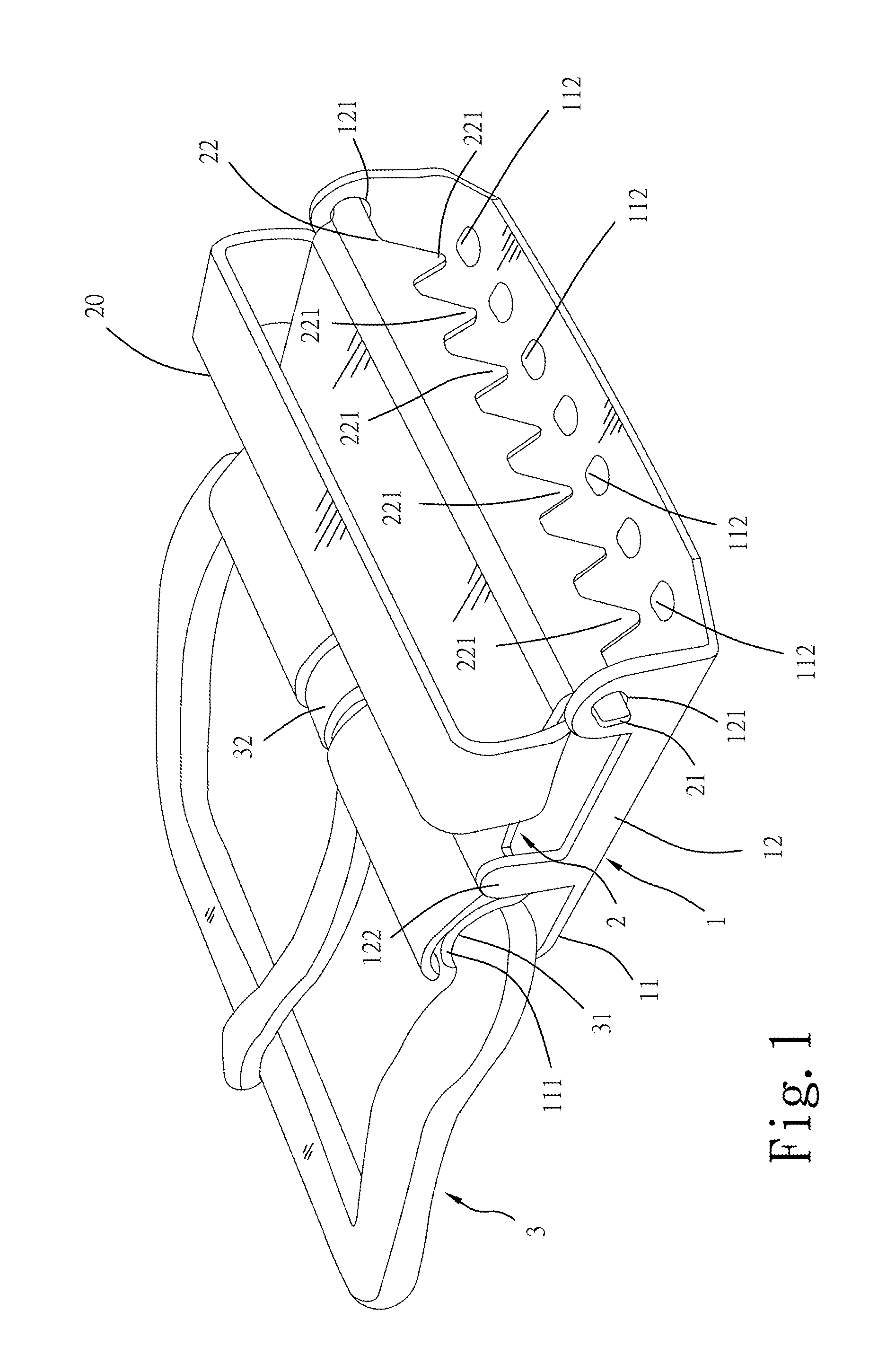
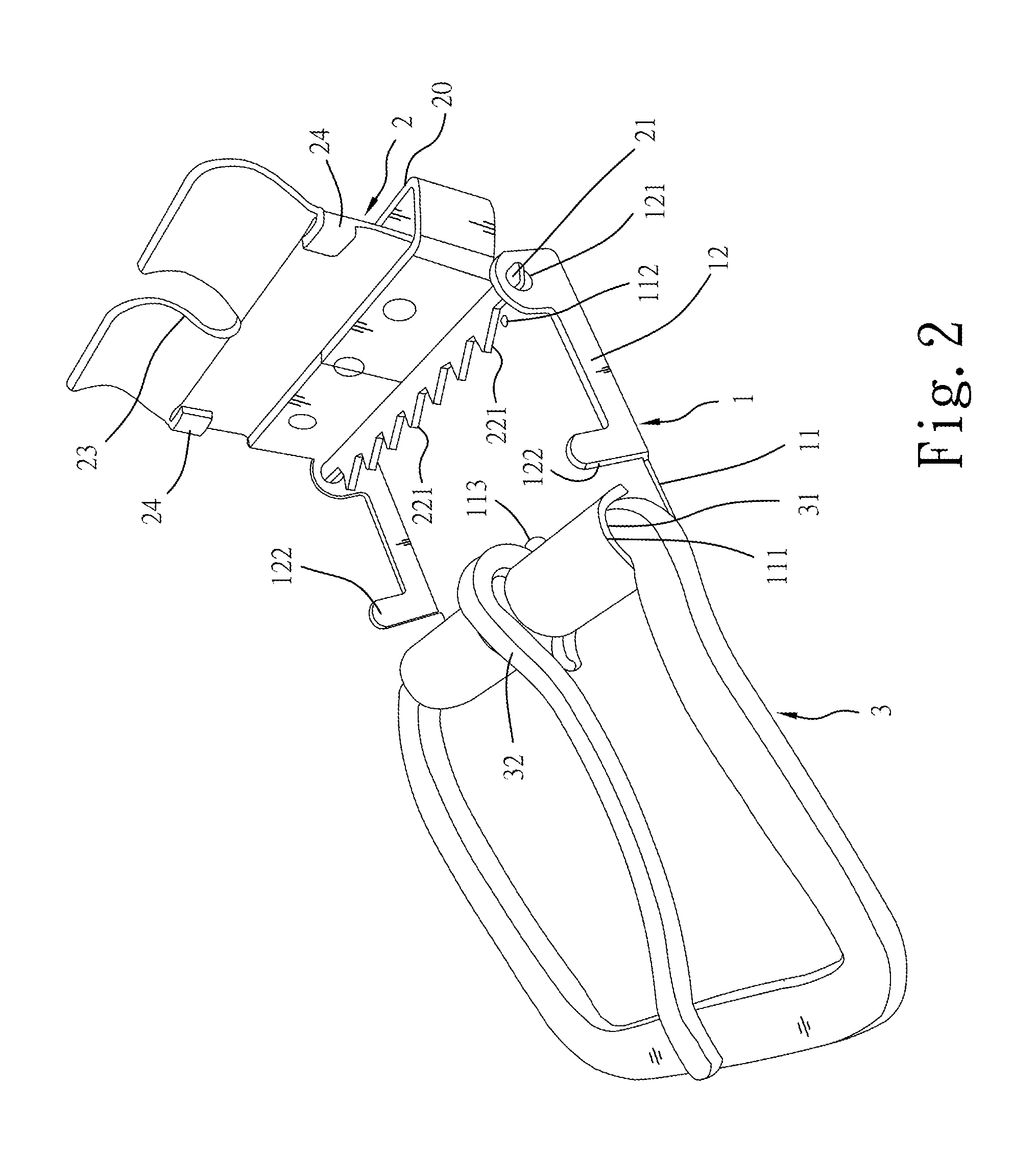
[0014]Referring to FIGS. 1-4, a belt buckle in accordance with the present invention is shown. The belt buckle comprises:

[0015]a buckle base 1 comprising a base panel 11, two upright side panel 12 respectively located at two opposite lateral sides of the base panel 11, a plurality of raised portion 112 located at a top surface of the base panel 11 for friction engagement with a bottom wall 42 of the belt 4 (see FIG. 3), a first pivot connection portion 111 located at a front side of the base panel 11 for the connection of a frame member 3, two second pivot connection portion 121 respectively located at the upright side panels 12 at a rear side for the connection of a clamping plate 2 (see FIG. 1 and FIG. 2), and a notch 113 located in a middle part of an opposing front side of the base panel 11 (see FIG. 2);

[0016]a clamping plate 2 comprising two third pivot connection portions 21 bilaterally disposed at a rear side thereof and respectively pivotally coupled to the second pivot conn...


PUM


Abstract

A belt buckle includes a buckle base having a plurality of raised portions at a base panel thereof for engagement with the bottom wall of the belt, a clamping plate pivotally connected to the buckle base and having a series of teeth for engagement with the top wall of the belt, a frame member pivotally connected to the buckle base, and a prong member pivotally coupled to the frame member.

Description

BACKGROUND OF THE INVENTION[0001]1. Field of the Invention[0002]The present invention relates to buckle technology, and more particularly, to a belt buckle, which comprises a buckle base having a plurality of raised portions at a base panel thereof for engagement with the bottom wall of the belt, a clamping plate pivotally connected to the buckle base and having a series of teeth for engagement with the top wall of the belt, a frame member pivotally connected to the buckle base, and a prong member pivotally coupled to the frame member.[0003]2. Description of the Related Art[0004]A conventional belt buckle generally has a clamping plate pivotally connected to a buckle base thereof and adapted for securing a belt to the buckle base. After insertion of one end of the belt in between the clamping plate and the buckle base, the clamping plate is biased toward the buckle base to force a series of teeth thereof into engagement with the top wall of the belt against the buckle base. However,...

Claims


Application Information

Patent Timeline
IPC IPC(8): A44B11/00A44B11/24
CPCA44B11/006Y10T24/4056A44B11/24A44B11/12Y10T24/3413Y10T24/4016Y10T24/4736
Inventor CHEN, SHYAN-WEICHEN, YA-CHI
Owner RACER SPORTING GOODS
Learn More