Connector assemblies, fluid systems including connector assemblies, and procedures for making fluid connections

a fluid system and connector technology, applied in the direction of hose connection, coupling, pipe coupling, etc., can solve the problems of high damage to the connection, dust or dirt in the fluid, and inability to so as to reduce the assembly force, enhance the reliability of the connection, and prevent accidental disconnection of the connector body

Active Publication Date: 2012-03-15
CYTIVA US LLC
View PDF15 Cites 8 Cited by
  • Summary
  • Abstract
  • Description
  • Claims
  • Application Information

AI Technical Summary

Benefits of technology

[0005]Devices and processes embodying these aspects of the invention provide many advantages. For example, by positioning the actuator around the coupling mechanism, the actuator surrounds and protects the coupled first ends and the coupling mechanism. This allows the connection provided by the coupling mechanism to be far more robust and tamper proof, preventing unintentional disassembly after actuation. In addition, by positioning the hollow piston between the first and second connector bodies and sealing the piston to the interiors of the connector bodies, the piston further reinforces the connection between the first and second bodies. This allows for the use of larger interiors in the connector bodies and piston, accommodating higher fluid flows through, and pressures within, the connector assembly.
[0008]Devices and methods embodying these aspects of the invention also provide many advantages. For example, the piston may be contained within the first connector body in the first position and within the coupled connector bodies in the second position to mechanically isolate the piston from any tubing or piping that is connected to the connector assembly. Consequently, the connections to the tubing or piping will not be loosened when the piston is moved from the first position to the second position, and any harmful mechanical forces exerted on the connector assembly by the tubing or piping are not transferred to piston. Further, rotating or twisting the actuator to move the piston reduces the assembly forces, virtually eliminating the possibility that the components will be damaged when the piston is moved to the second position.
[0009]For some embodiments, the moveable actuator may be arranged not only to move the piston to the second position in response to movement of the actuator but also to maintain the piston in the second position. For example, the actuator may be locked in place once the piston is moved to the second position. Alternatively, further movement of the actuator after the piston is moved to the second position may uncouple the actuator from the piston, leaving the piston in the second position. In either event, accidental disconnection of the connector bodies is prevented, enhancing the reliability of the connection.
[0010]For some embodiments, the first ends of the first and second connector bodies may be covered by a seal layer. The seal layer may be arranged to be removed, for example, after the first ends of the connector bodies are coupled and before the piston is moved to the second piston. This prevents contamination of the interiors of the first and second bodies and the piston and helps provide a sterile connection.

Problems solved by technology

The introduction into the fluid of unwanted contaminants, including biological contaminants, such as viruses or minute organisms, e.g., bacteria, and environmental contaminants, such as dust or dirt, can be highly detrimental for a great variety of reasons.

Method used


Image

  • Connector assemblies, fluid systems including connector assemblies, and procedures for making fluid connections
  • Connector assemblies, fluid systems including connector assemblies, and procedures for making fluid connections
  • Connector assemblies, fluid systems including connector assemblies, and procedures for making fluid connections

Examples


Embodiment Construction

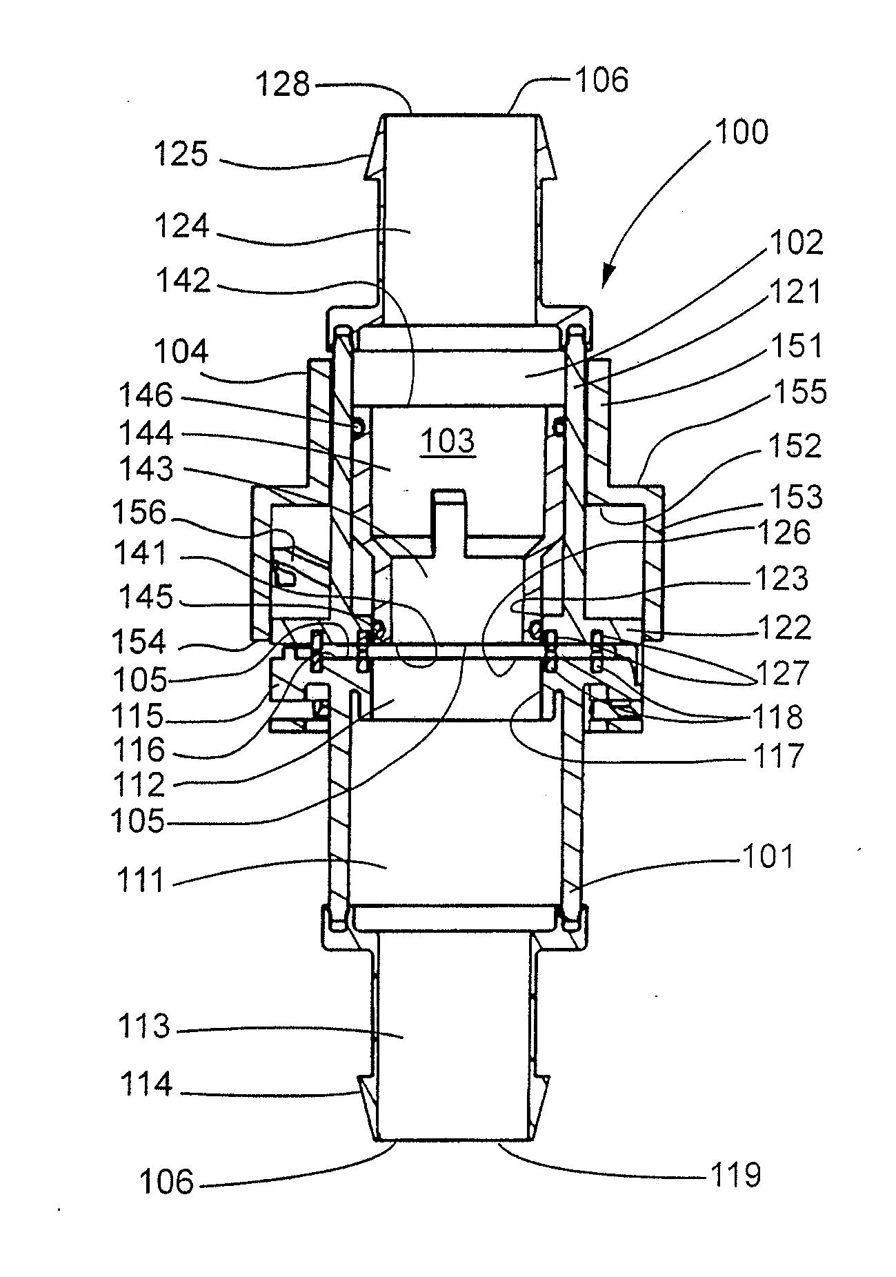
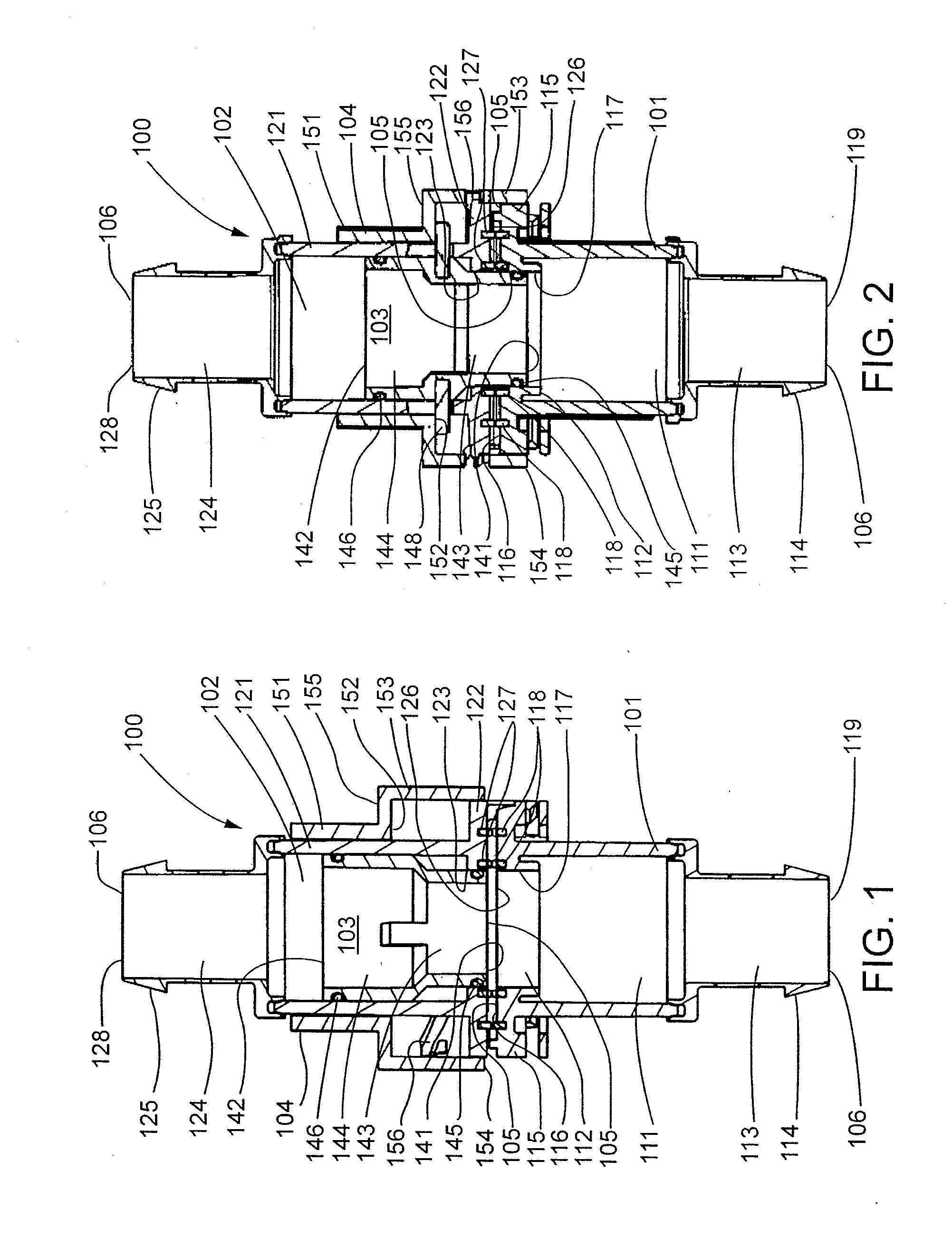
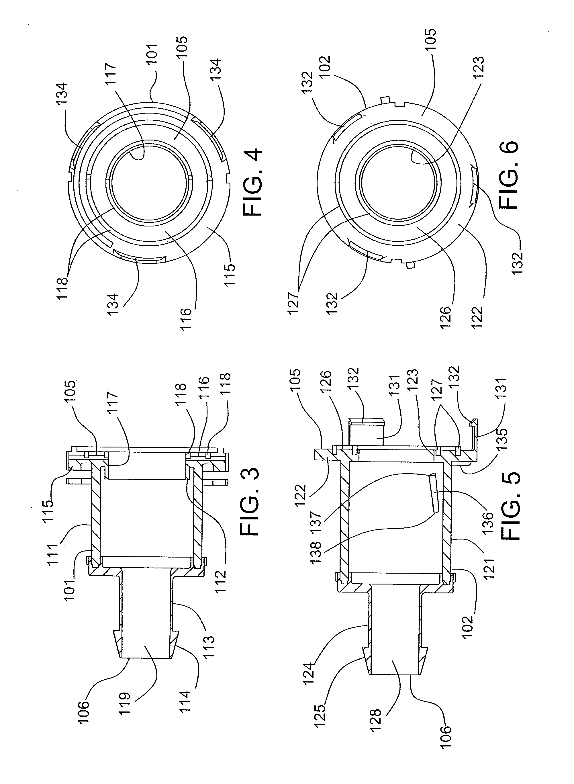
[0028]Connector assemblies embodying the invention may be configured in a wide variety of ways, and one of many different examples is shown in FIGS. 1 and 2. The exemplary connector assembly 100 may comprise female and male hollow connector bodies 101, 102, a moveable hollow piston 103, and a moveable actuator 104. Each connector body 101, 102 has first and second ends 105, 106, and the connector bodies 101, 102 may be coupled to one another at their first ends 105 by a coupling mechanism 107. All, or at least a portion, of the moveable piston 103 may initially be located in the interior of the male body 102. The moveable actuator 104 may be mounted on the exterior of at least one, or both, of the connector bodies 101, 102 and may be coupled to the moveable piston 103. In the illustrated embodiment, the actuator 104 may be moveably mounted to the male connector body 102 and may be coupled to the piston 103 through the male body 102. In response to movement of the actuator 104 from a...


PUM


Abstract

A connector assembly has first and second connector bodies, a coupling mechanism arranged to couple the connector bodies at the first ends of the bodies, a moveable hollow piston, and a moveable actuator. The hollow piston moves from a first position to a second position in response to movement of the actuator from a first position to a second position. In the second position the hollow piston is sealed to the interiors of first and second connector bodies.

Description

FIELD OF THE INVENTION[0001]The present invention is useful in many different industries, including the biopharmaceutical, biotechnology, food, beverage, cosmetic, and medical industries. In all of these industries, large or small systems of pipes, tubes, hoses and other conduits channel fluids from one location to another. The fluids may be gases, liquids, or mixtures of gases, liquids and / or solids. Many of these fluid systems, including biopharmaceutical and medical systems, transfer these fluids from one sterile location to another sterile location and have very strict requirements for sterility. The introduction into the fluid of unwanted contaminants, including biological contaminants, such as viruses or minute organisms, e.g., bacteria, and environmental contaminants, such as dust or dirt, can be highly detrimental for a great variety of reasons.[0002]It is often necessary to make fluid connections in these systems, for example, to connect or disconnect existing conduits or c...

Claims


Application Information

Patent Timeline
Patent Type & Authority Applications(United States)
IPC IPC(8): F16L25/00
CPCF16L37/248A61M39/1011F16L2201/44F16L29/005F16L37/107A61M39/18A61M5/14F16L37/24
Inventor STELL, ADRIAN
Owner CYTIVA US LLC
Why Eureka
Try Eureka