Power transmission control device, power transmission device, non-contact power transmission system, and electronic instrument

a power transmission device and control device technology, applied in the direction of instruments, electrochemical generators, transportation and packaging, etc., can solve the problems of instruments breaking down and abnormal heat generation, and achieve the effect of reducing the number of parts and reducing the size and cost of non-contact power transmission devices

Active Publication Date: 2011-09-27
SEIKO EPSON CORP
View PDF11 Cites 35 Cited by
  • Summary
  • Abstract
  • Description
  • Claims
  • Application Information

AI Technical Summary

Benefits of technology

[0050]FIGS. 17A to 17E are views illustrative of an operation of reducing the load state of a power-supply-target load (e.g., battery).
[0135]This makes it possible to provide a high-performance electronic instrument with low power consumption and improved safety and reliability.
[0051]Several embodiments of the invention may provide non-contact power transmission technology that improves convenience to the user and thoroughly reduce power consumption, for example. Several embodiments of the invention may provide highly reliable non-contact power transmission technology that ensures appropriate safety measures, for example. Several embodiments of the invention may provide non-contact power transmission technology that sufficiently takes convenience to the user into account, for example. Several embodiments of the invention may provide non-contact power transmission technology that reduces the size and the cost of a non-contact power transmission device by reducing the number of parts, for example.

Problems solved by technology

For example, when power is transmitted to a non-standard secondary-side instrument, the instrument may break down.
For example, when power is transmitted in a state in which a metal foreign object is present, abnormal heat generation may occur.

Method used


Image

  • Power transmission control device, power transmission device, non-contact power transmission system, and electronic instrument
  • Power transmission control device, power transmission device, non-contact power transmission system, and electronic instrument
  • Power transmission control device, power transmission device, non-contact power transmission system, and electronic instrument

Examples


first embodiment

[0137]Examples of an electronic instrument to which the invention is suitably applied and the principle of non-contact power transmission technology are described below.

[0138]Examples of Electronic Instrument and Principle of Non-Contact Power Transmission

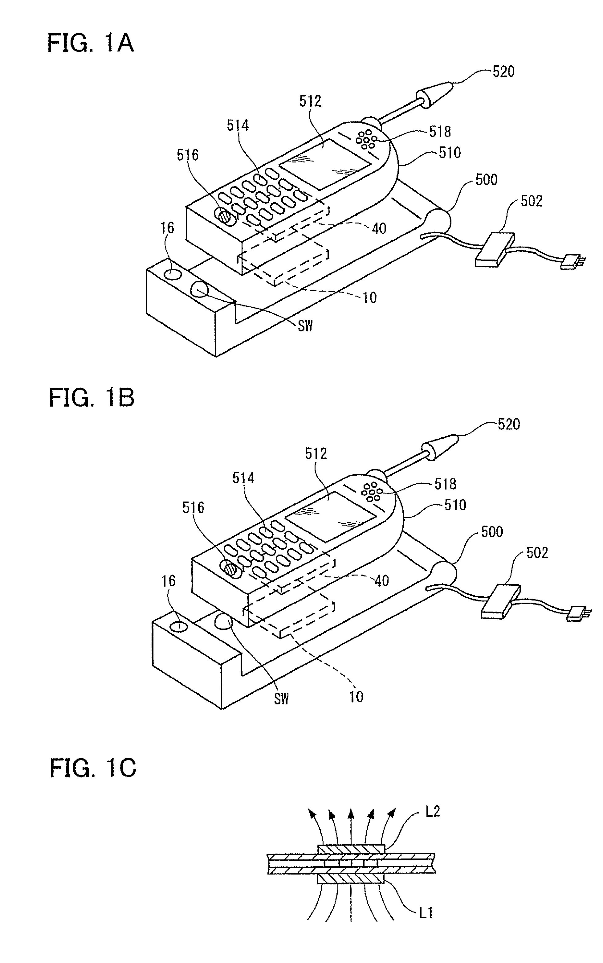
[0139]FIGS. 1A to 1C are views illustrative of examples of an electronic instrument compliant with non-contact power transmission and the principle of non-contact power transmission using an induction transformer

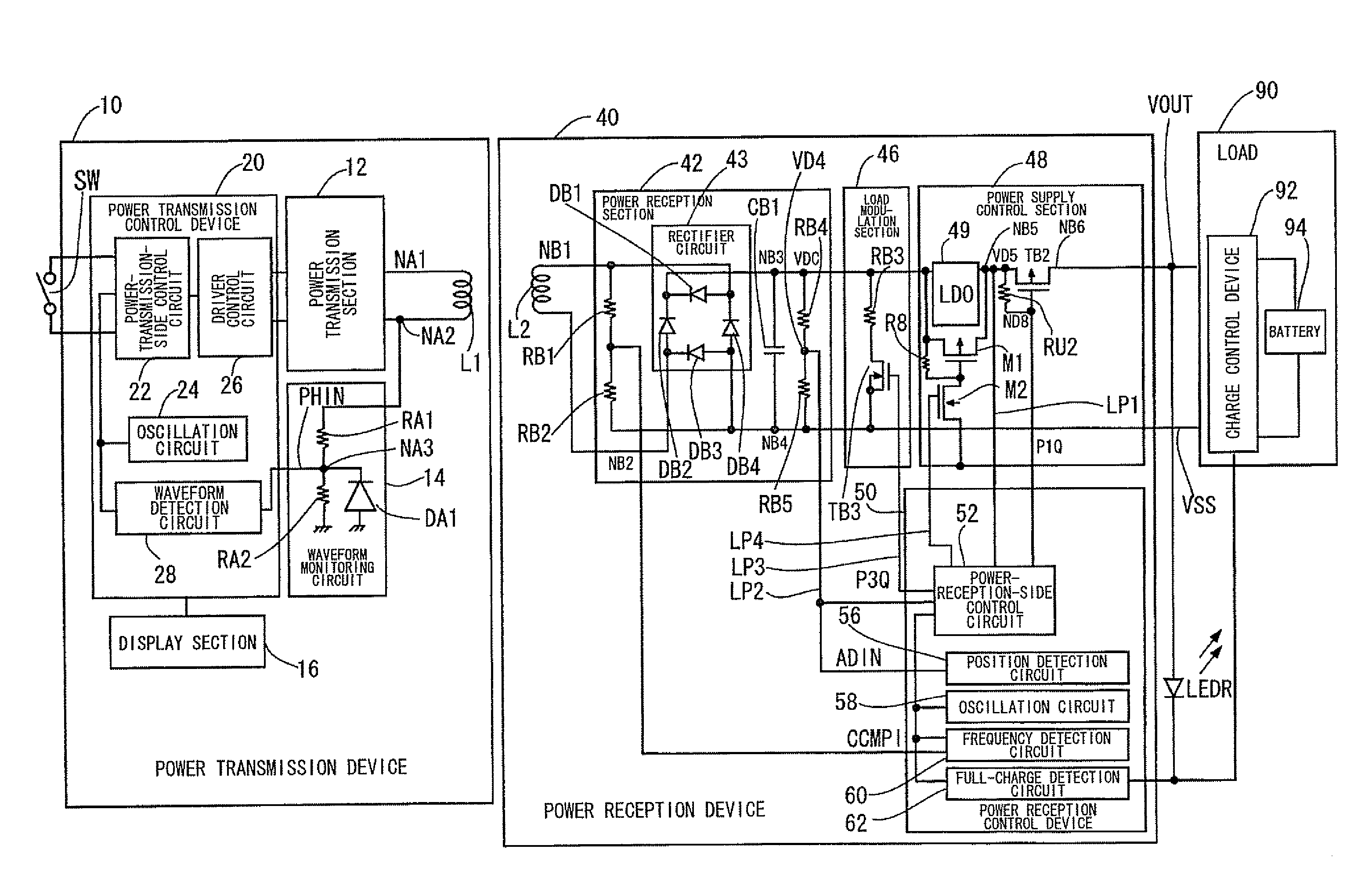
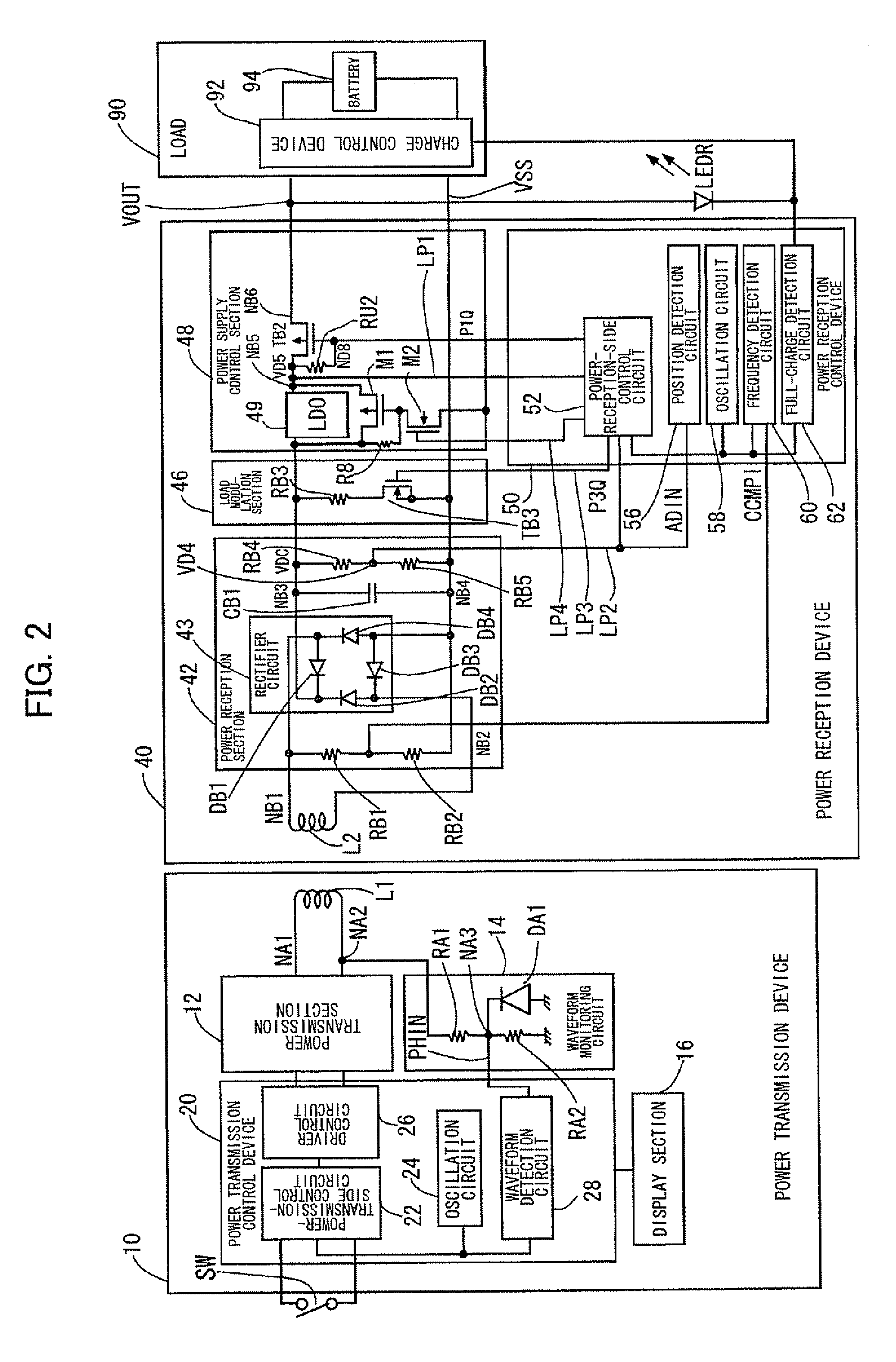
[0140]As shown in FIGS. 1A and 1B, a charger (cradle) 500 (i.e., power-transmission-side electronic instrument) includes a power transmission device (e.g., power transmission module including a power-transmission-side control circuit (power-transmission-side control IC)) 10.

[0141]The charger (cradle) 500 also includes a switch (SW) that causes (triggers) power transmission to start or stop, and a display section (e.g., LED) 16 that is turned ON when the charger transmits power (operates).

[0142]In the charger (cradle) 500 sh...

second embodiment

[0245]This embodiment illustrates the details of takeover state detection (measures against takeover heat generation).

[0246]Measures Against Takeover Heat Generation

[0247]A large foreign object may be inserted between the primary coil and the secondary coil after the instrument has been authenticated and normal power transmission has started. A small or medium-sized metal foreign object can be detected by monitoring the induced voltage in the primary coil (L1), as described with reference to FIG. 11.

[0248]However, when a large metal foreign object (e.g., thin metal sheet) that blocks the primary coil and the secondary coil has been inserted between the primary-side instrument and the secondary-side instrument (see FIGS. 13A and 13B), the energy transmitted from the primary-side instrument is consumed by the metal foreign object (i.e., the metal foreign object acts as a load). Therefore, the primary-side instrument regards the metal foreign object as the secondary-side instrument. Ac...


PUM

PropertyMeasurementUnit
voltageaaaaaaaaaa
timeaaaaaaaaaa
time t1aaaaaaaaaa

Abstract

A power-transmission-side control circuit causes a power transmission device to perform temporary power transmission when a switch provided in a power-transmission-side instrument has been turned ON, and performs ID authentication based on ID authentication information. The power-transmission-side control circuit detects the presence or absence of a foreign object during normal power transmission by monitoring a change in induced voltage in a primary coil, causes the power transmission device to stop temporary power transmission when the ID authentication information from the power reception device has not been received within a given period of time, causes the power transmission device to stop temporary power transmission when the ID authentication has failed, and causes the power transmission device to stop normal power transmission when removal, a metal foreign object, a takeover state, or a full-charge state has been detected after normal power transmission has started.

Description

[0001]Japanese Patent Application No. 2007-172489 filed on Jun. 29, 2007, is hereby incorporated by reference in its entirety.BACKGROUND OF THE INVENTION[0002]The present invention relates to a power transmission control device, a power transmission device, a non-contact power transmission system, and an electronic instrument.[0003]In recent years, non-contact power transmission (contactless power transmission) that utilizes electromagnetic induction to enable power transmission without metal-to-metal contact has attracted attention. As application examples of non-contact power transmission, charging a portable telephone, a household appliance (e.g., cordless telephone handset or watch), and the like has been proposed.[0004]JP-A-2006-60909 discloses a non-contact power transmission device using a primary coil and a secondary coil, for example.[0005]A non-contact power transmission device is strongly desired to consume only a small amount of power in order to increase the life of a b...

Claims


Application Information

Patent Timeline
Patent Type & Authority Patents(United States)
IPC IPC(8): H01M10/46H02J7/00G06F21/44
CPCH02J5/005G01V3/10H02J7/025H04B5/0037H02J7/00045H02J7/0044H02J50/80H02J50/90H02J50/12H02J50/60
Inventor KAMIJO, TAKAHIROHASEGAWA, MINORUSOGABE, HARUHIKOONISHI, KOTAKAMIYAMA, MASAYUKISHIOZAKI, NOBUTAKA
Owner SEIKO EPSON CORP
Why Eureka
Try Eureka