
Method for monitoring a grinding system and grinding system comprising a monitoring device

A technology of grinding parts and grinding rollers, which is used in the field of monitoring the load status of grinding systems and can solve problems such as non-compliance with requirements

Active Publication Date: 2011-08-03
KRUPP POLYSIUS AG
View PDF1 Cites 9 Cited by
  • Summary
  • Abstract
  • Description
  • Claims
  • Application Information

AI Technical Summary

Problems solved by technology

However, this approach is also not satisfactory with respect to monitoring reliability and sensitivity on large grinding systems

Method used


Image

  • Method for monitoring a grinding system and grinding system comprising a monitoring device
  • Method for monitoring a grinding system and grinding system comprising a monitoring device
  • Method for monitoring a grinding system and grinding system comprising a monitoring device

Examples


Embodiment Construction

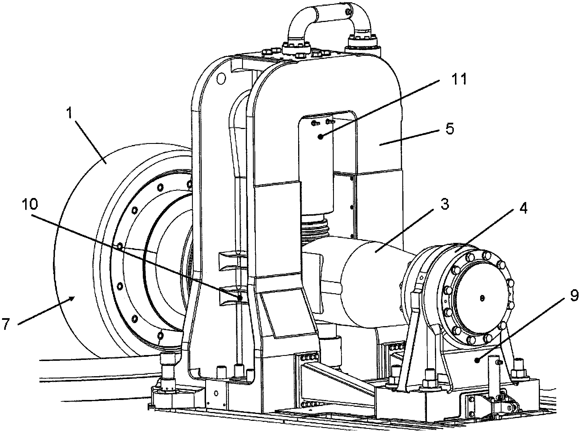
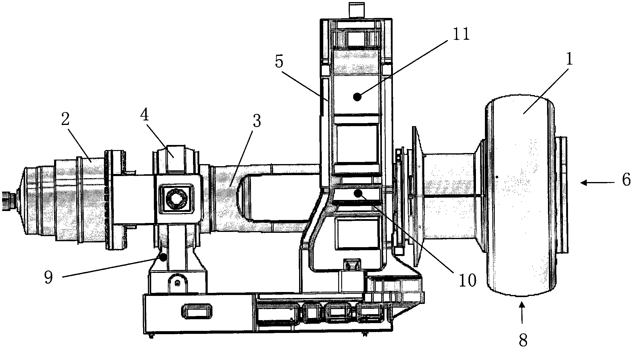
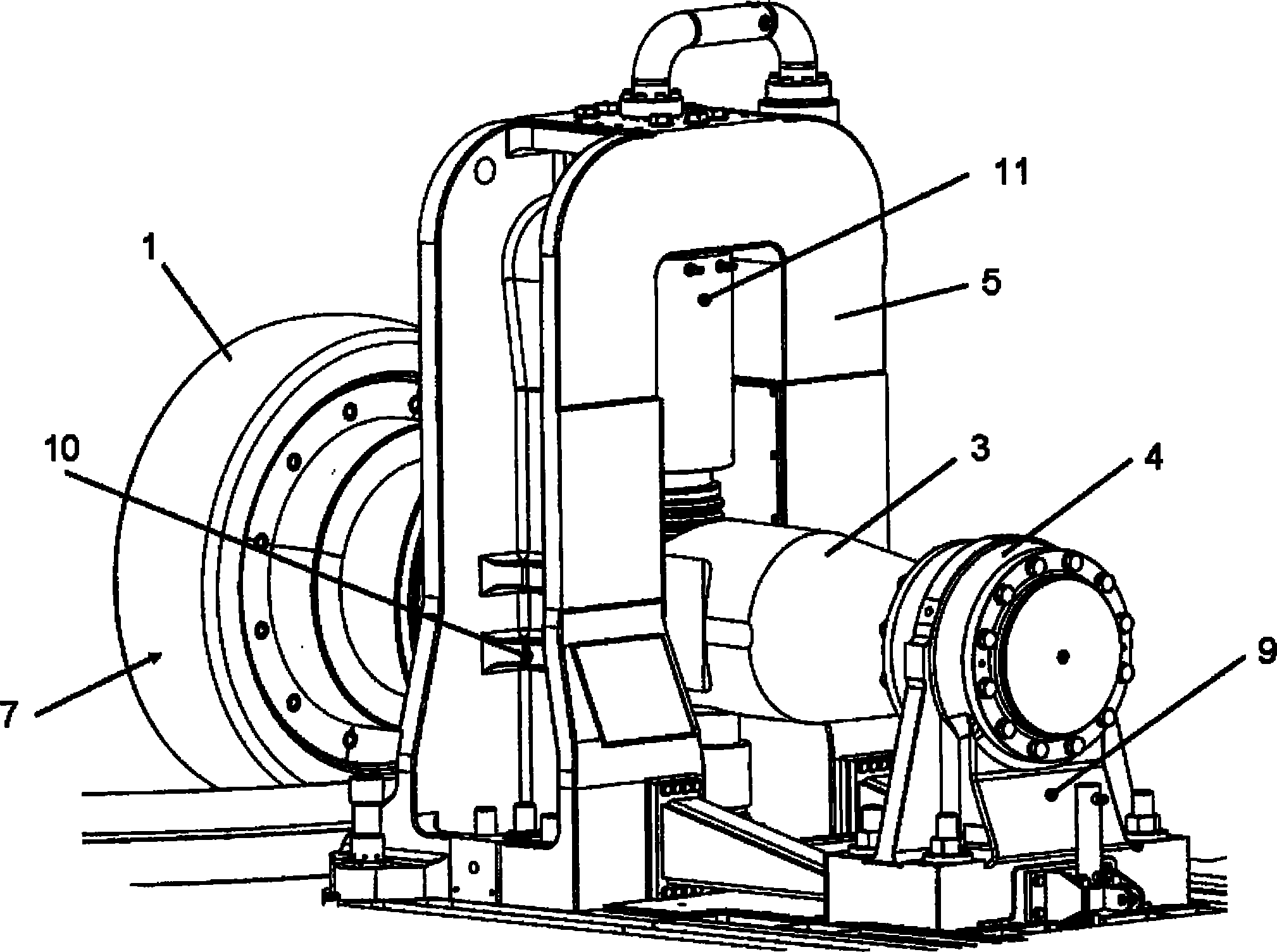
[0015] The grinding roll 1 runs on a grinding table (not shown) of a vertical roller mill and can be driven directly by a drive motor 2 with a transmission shaft surrounded by a spindle 3 - as shown in this example, or indirectly via the grinding table to drive.

[0016] On the side facing the drive motor 2, the transmission shaft is arranged in a fixed bearing 4, while on the side facing the grinding roller 1, the transmission shaft is arranged in a movable Bearing 5.

[0017] In operation, power is applied to the grinding roller 1 through the abrasive in the axial direction (arrow 6), tangential direction (arrow 7) and vertical direction (arrow 8).

[0018] The forces acting in the axial direction in the fixed bearing 4 are measured by means of an extension measuring sensor 9 mounted on the fixed bearing 4 .

[0019] The force acting tangentially in the movable bearing 5 is determined by means of an extension measurement sensor 10 arranged on said movable bearing 5 .

[0...


PUM


Abstract

The invention relates to a method for monitoring the load state of a grinding system comprising rotating grinding elements, wherein the dynamic forces exerted by the ground material onto the grinding elements are detected in a first frequency range containing the base vibration of the grinding elements and in a second frequency range in which the first harmonic of the base vibration occurs, whereupon actions for reducing the load state are introduced if the first harmonic exceeds a pre-determined threshold relative to the magnitude of the base vibration. Such a method enables a very reliable and precise monitoring of the load state of the grinding system.

Description

technical field [0001] The invention relates to a method for monitoring the load state of a grinding system and a grinding system equipped with such a monitoring device. Background technique [0002] It is known to monitor grinding systems, such as roller mills, by means of sensors to detect the vibration rate of the individual grinding parts and of the entire grinding system and to monitor the frequency range in the control device of the grinding system with respect to predetermined limit values ​​according to ISO 10816-3 The effective value of the vibration rate between 10 and 1000 Hz, the so-called RMS value (root mean square value). [0003] However, according to the investigations and measurements carried out, the known vibration monitoring by said RMS is not completely reliable, because, on the one hand, it sometimes detects critical load states too late or not at all, and on the other hand, even The critical load condition has not been reached and it will occasionall...

Claims


Application Information

Patent Timeline
Patent Type & Authority Applications(China)
IPC IPC(8): B02C25/00B02C15/00
CPCB02C15/00B02C15/04B02C25/00
Inventor C·斯帕茨M·伯杰F-J·祖霍夫R·奥斯特卡姆帕L·可梅耶M·乌沃P·格雷罗帕尔马
Owner KRUPP POLYSIUS AG
Learn More