
Method for monitoring a grinding system and grinding system comprising a monitoring device

a technology of monitoring device and grinding system, which is applied in the direction of measurement device, force/torque/work measurement apparatus, instruments, etc., can solve the problems of not meeting the requirements of reliability and sensitivity, and the known vibration monitoring method using the rms value is not entirely reliable, so as to achieve reliable and accurate monitoring of the load state

Active Publication Date: 2013-11-26
THYSSENKRUPP POLYSIUS AKTIENGES
View PDF10 Cites 0 Cited by
  • Summary
  • Abstract
  • Description
  • Claims
  • Application Information

AI Technical Summary

Benefits of technology

The invention provides a method and grinding system that can accurately monitor the load state of the grinding system. This is important because it allows for timely maintenance and repair of the grinding system, reducing downtime and improving efficiency. The method introduces measures to reduce the load state when the first harmonic exceeds a predetermined value in relation to the magnitude of the fundamental oscillation. Overall, the technical effects of the invention are improved reliability and accuracy of grinding system load state monitoring.

Problems solved by technology

Investigations and measurements carried out have shown, however, that that known vibration monitoring by means of the RMS value is not entirely reliable since, on the one hand, it sometimes detects critical load states too late or not at all while, on the other hand, it occasionally responds even though a critical load state has not yet been reached.
However, nor does that method meet the demands with respect to reliability and sensitivity made on the monitoring of large grinding systems.

Method used


Image

  • Method for monitoring a grinding system and grinding system comprising a monitoring device
  • Method for monitoring a grinding system and grinding system comprising a monitoring device
  • Method for monitoring a grinding system and grinding system comprising a monitoring device

Examples


Embodiment Construction

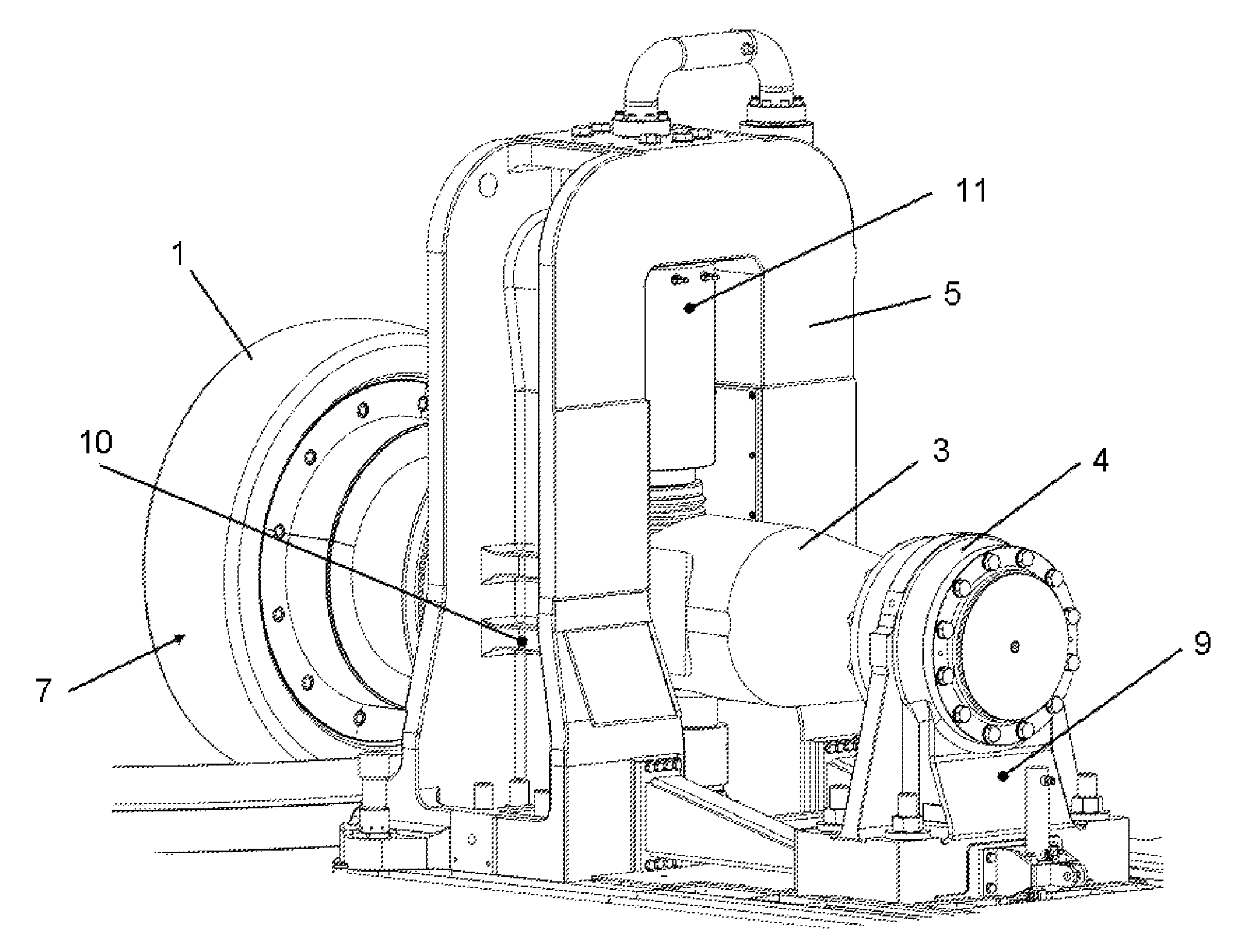
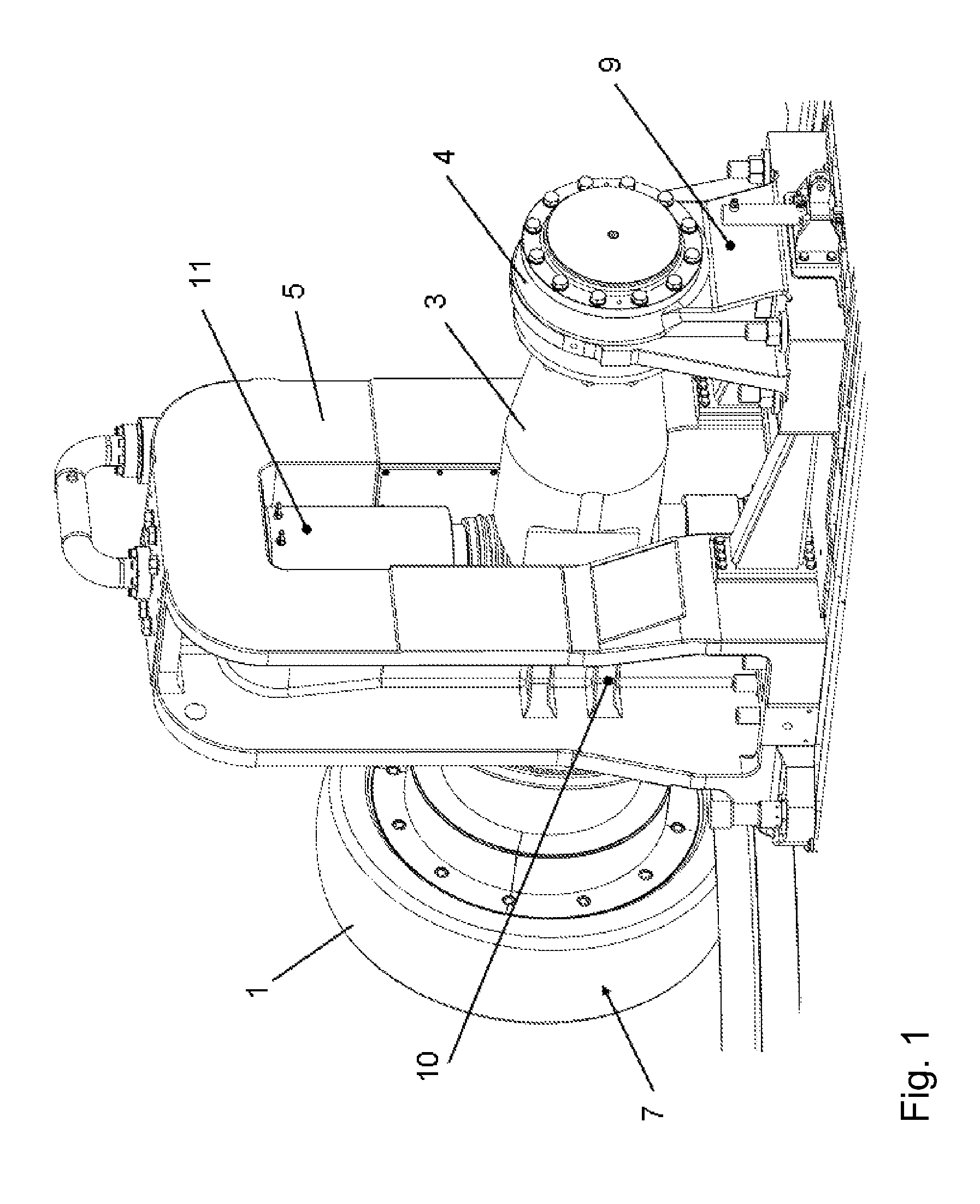
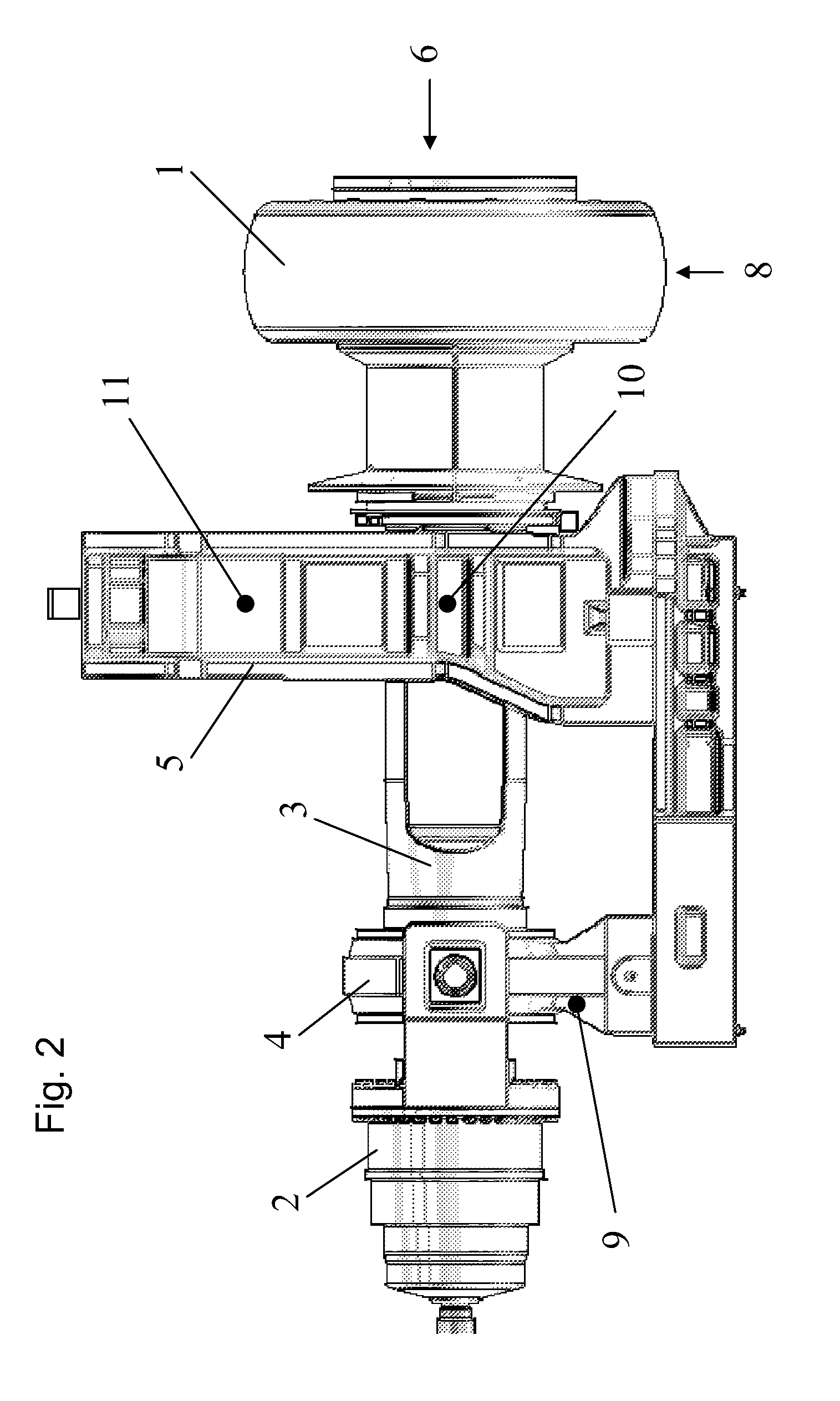
[0016]The grinding roller 1 runs on the grinding table (not shown) of a vertical roller mill and can be driven either directly—as in the embodiment shown—by a drive motor 2 by way of a shaft surrounded by an arbor 3, or indirectly by way of the grinding table.

[0017]On the side facing the drive motor 2, the shaft is arranged in a stationary bearing 4 and, on the side facing the grinding roller 1, it is arranged in a movable bearing 5 constructed as a force frame.

[0018]In operation, dynamic forces are exerted by the grinding stock on the grinding roller 1 in the axial direction (arrow 6), the tangential direction (arrow 7) and the vertical direction (arrow 8).

[0019]The forces acting in the axial direction are detected in the stationary bearing 4 by an extension measurement sensor 9 fitted there.

[0020]The forces acting in the tangential direction are ascertained in the movable bearing 5 by an extension measurement sensor 10 provided there.

[0021]The forces acting in the vertical directi...


PUM

PropertyMeasurementUnit
frequencyaaaaaaaaaa
frequencyaaaaaaaaaa
frequencyaaaaaaaaaa

Abstract

The invention relates to a method for monitoring the load state of a grinding system having rotating grinding elements, the dynamic forces exerted by the grinding stock on the grinding elements being detected in a first frequency range which contains the fundamental oscillation of the grinding elements, and in a second frequency range in which the first harmonic of the fundamental oscillation occurs, and measures for reducing the load state being introduced when the first harmonic exceeds a predetermined threshold value in relation to the magnitude of the fundamental oscillation. Such a method permits very reliable and accurate monitoring of the load state of the grinding system.

Description

TECHNICAL FIELD[0001]The invention relates to a method for monitoring the load state of a grinding system and to a grinding system equipped with such a monitoring device.BACKGROUND OF THE INVENTION[0002]In order to monitor grinding systems, for example roller mills, it is known to detect the vibration rate of the individual grinding elements and of the entire grinding system by means of sensors and to monitor with respect to predetermined limiting values the effective value of the vibration rate in the frequency range of from 10 to 1000 Hz in accordance with ISO 10816-3, the so-called RMS value (Root-Mean-Square), in the control arrangement of the grinding system.[0003]Investigations and measurements carried out have shown, however, that that known vibration monitoring by means of the RMS value is not entirely reliable since, on the one hand, it sometimes detects critical load states too late or not at all while, on the other hand, it occasionally responds even though a critical loa...

Claims


Application Information

Patent Timeline
Patent Type & Authority Patents(United States)
IPC IPC(8): G01N3/00
CPCB02C15/00B02C15/04B02C25/00
Inventor SPEITH, CHRISTIANBERGER, MARKUSZURHOVE, FRANZ-JOSEFOSTKAMP, RUDIGERKIMMEYER, LUDGERWUWER, MATTHIASPALMA, PEDRO GUERRERO
Owner THYSSENKRUPP POLYSIUS AKTIENGES
Learn More