
Stereo matching system and stereo matching method using the same

a matching system and stereo technology, applied in the field of stereo matching system and stereo matching method, can solve problems such as false matching

Active Publication Date: 2011-10-25
SAMSUNG DISPLAY CO LTD
View PDF14 Cites 10 Cited by
  • Summary
  • Abstract
  • Description
  • Claims
  • Application Information

AI Technical Summary

Benefits of technology

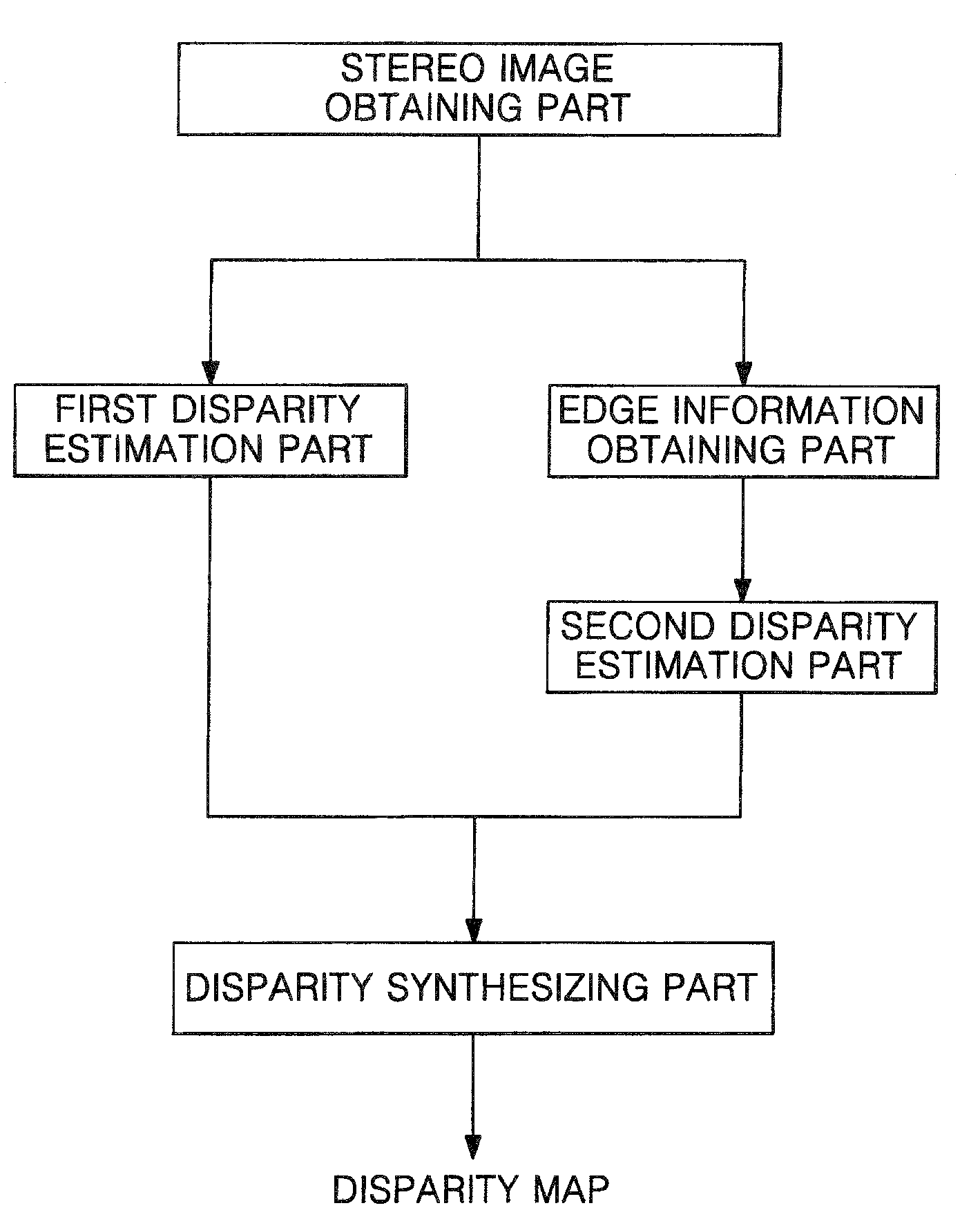
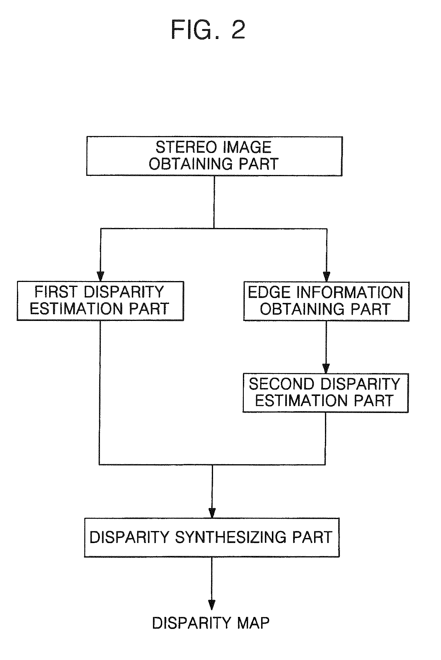
The present invention provides a stereo matching system and method using a combination of edge information and a local method to correct false matching in a non-texture region. The system includes a stereo image obtaining part, an edge information obtaining part, a second disparity estimation part, and a disparity synthesizing part. The method involves estimating the disparity of the left and right images using a local method and edge information, and then synthesizing the disparities using a combination of the SED and the local method. The technical effects of the invention include improved accuracy and efficiency in stereo matching, particularly in regions with no texture, and reduced computational complexity.

Problems solved by technology

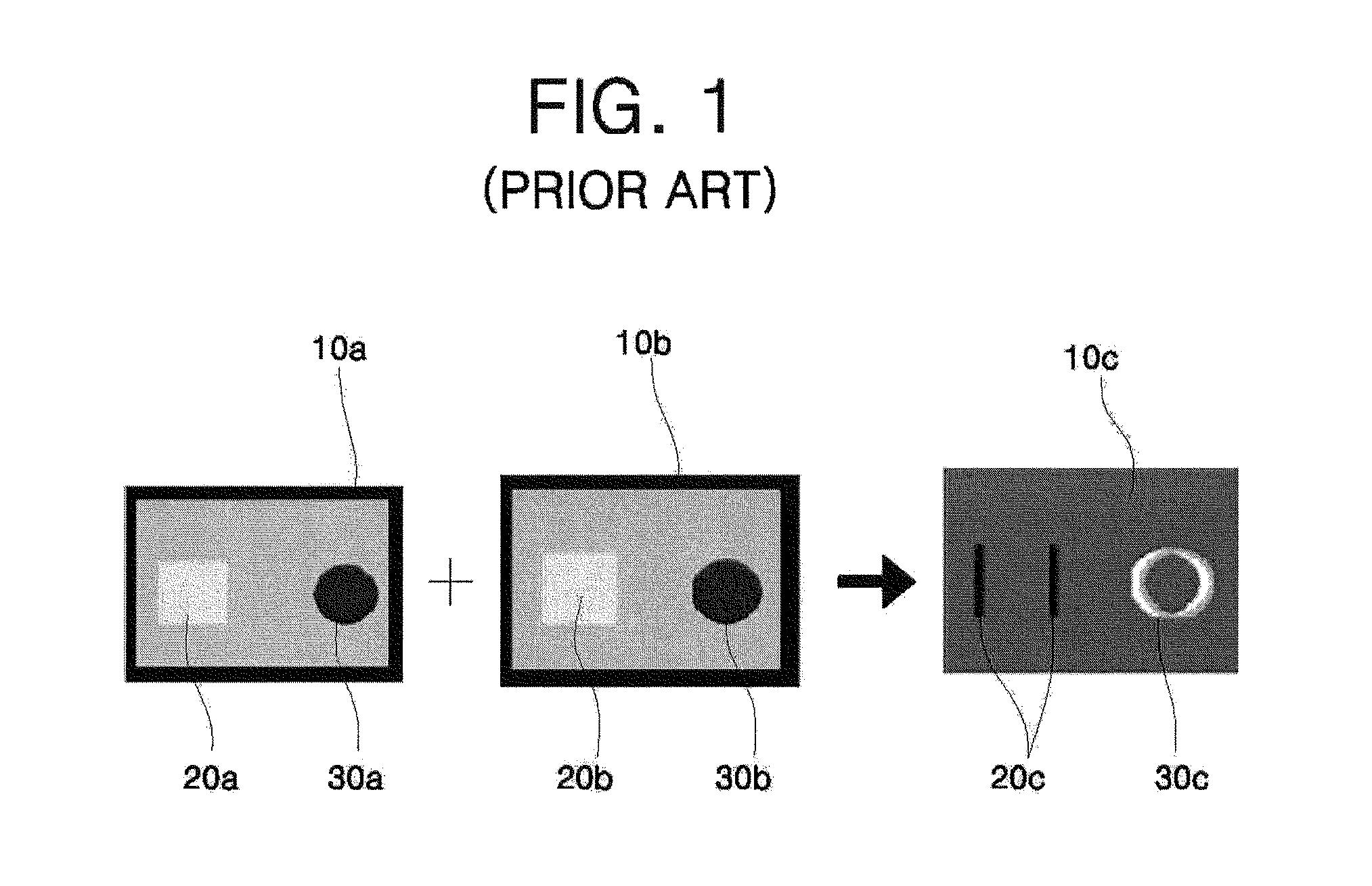
However, since the local method uses the light and shade information only, it is difficult to precisely find similar images in a non-texture region, thereby causing false matching.

Method used


Image

  • Stereo matching system and stereo matching method using the same
  • Stereo matching system and stereo matching method using the same
  • Stereo matching system and stereo matching method using the same

Examples


exemplary embodiment 1

[0090]FIGS. 5A to 5C are photographs showing a first exemplary embodiment in accordance with the present invention.

[0091]First, FIG. 5A is a disparity map representing actual disparity of an image. FIG. 5B is a disparity map obtained by the SAD disparity estimation method utilizing a local method. FIG. 5C is a disparity map of the first exemplary embodiment in which the SED disparity estimation method utilizing edge information is added to the SAD method.

[0092]Here, the photograph of FIG. 5C can be obtained by the stereo matching system including the stereo image obtaining part, the first disparity estimation part, the edge information obtaining part, the second disparity estimation part, and the disparity synthesizing part, which have been described with reference to FIG. 2. Operation of the stereo matching system will be described below.

[0093]First, the stereo image obtaining part performs a first step of obtaining a left image and a right image.

[0094]Next, the first disparity est...

exemplary embodiment 2

[0110]FIGS. 7A to 7C are photographs showing a second exemplary embodiment in accordance with the present invention.

[0111]First, FIG. 7A is a disparity map representing actual disparity of an image.

[0112]FIG. 7B is a disparity map obtained by an SAD disparity estimation method using a local method.

[0113]FIG. 7C is a disparity map in which an SED disparity estimation method using edge information is added to the SAD method.

[0114]Here, the photograph of FIG. 7C can be obtained by the stereo matching system including the stereo image obtaining part, the first disparity estimation part, the edge information obtaining part, the second disparity estimation part, and the disparity synthesizing part, which have been described with reference to FIG. 2. Operation of the stereo matching system will be described below.

[0115]First, the stereo image obtaining part performs a first step of obtaining a left image and a right image.

[0116]Next, the first disparity estimation part estimates disparity ...


PUM


Abstract

A stereo matching system and a stereo matching method using the same. Here, a Sum of Edge Differences (SED) method as a disparity estimation method utilizing edge information is added to a disparity estimation method utilizing a local method to perform stereo matching. As such, it is possible to correct false matching in a non-texture region generated when stereo matching is performed using only a local method, thereby enabling good stereo matching.

Description

CROSS-REFERENCE TO RELATED APPLICATION[0001]This application claims priority to and the benefit of Korean Patent Application No. 10-2007-0078562, filed Aug. 6, 2007, the entire content of which is incorporated herein by reference.BACKGROUND OF THE INVENTION[0002]1. Field of the Invention[0003]The present invention relates to a stereo matching system and a stereo matching method using the same.[0004]2. Description of the Related Art[0005]In general, stereo matching refers to estimating disparity as a distance between corresponding points of two images that are obtained by different view points using distance perception ability in a human visual system, and to obtaining a precise and reliable disparity map.[0006]In addition, the disparity map is implemented as a depth map to recover a three-dimensional image for providing depth perception.[0007]Stereo matching may be used in various fields, such as information communication, broadcasting, medicine, games, displays, and so on, which ma...

Claims


Application Information

Patent Timeline
Patent Type & Authority Patents(United States)
IPC IPC(8): G06K9/00G06K9/48
CPCG06T7/0075G06T2207/10012G06T7/593H04N13/00
Inventor KU, JA-SEUNGNAM, HUIPARK, CHAN-YOUNGKIM, BEOM-SHIK
Owner SAMSUNG DISPLAY CO LTD
Learn More