Three-dimensional photographing process based on laser probe array and device utilizing same

A laser probe and array technology, applied in the direction of optical devices, photography, measuring devices, etc., can solve the problems of small measurement area, shadow blocking, and inability to quickly provide dense three-dimensional coordinates

Inactive Publication Date: 2012-06-13
李志扬
View PDF5 Cites 66 Cited by
  • Summary
  • Abstract
  • Description
  • Claims
  • Application Information

AI Technical Summary

Problems solved by technology

For example, measurement technology based on laser triangulation and laser scanning technology based on time-of-flight generally use point-to-point measurement methods, which cannot quickly provide large-area dense three-dimensional coordinates; although laser interferometry technology has high precision, it is prone to laser noise and vibration interference , and the measurement area is small; another example is that although various structured light projection measurement technologies have good measurement accuracy, the measurement depth and width generally do not exceed 5 meters, and shadow occlusion problems often occur.

Method used


Image

  • Three-dimensional photographing process based on laser probe array and device utilizing same
  • Three-dimensional photographing process based on laser probe array and device utilizing same
  • Three-dimensional photographing process based on laser probe array and device utilizing same

Examples


Embodiment 1

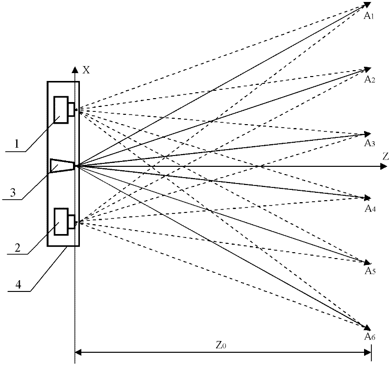
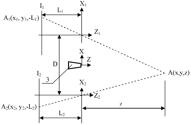
[0040] Step 1. Set the optical center of the laser probe generator as the coordinate origin, the optical axis of the laser probe generator is the Z axis, the X axis is perpendicular to the Z axis, the X axis Z axis plane is the horizontal plane, and the Y axis is perpendicular to the X axis Z axis plane; the first two-dimensional camera and the second two-dimensional camera are arranged symmetrically on both sides of the origin on the X axis, and the optical axes of the first two-dimensional camera and the second two-dimensional camera are parallel to the Z axis, so that the first two-dimensional camera and the second two-dimensional camera are The second two-dimensional camera constitutes a pair of stereoscopic cameras, while the first two-dimensional camera and the second two-dimensional camera respectively form a three-dimensional measurement device based on the laser probe array with the laser probe generator;

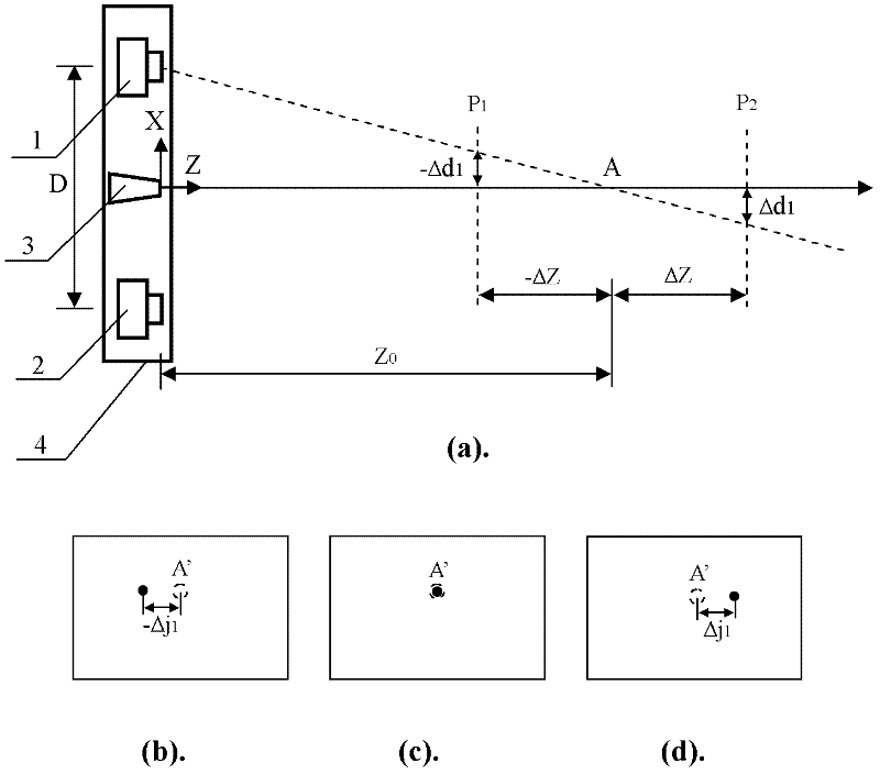
[0041] Step 2, setting the predetermined focus point of the la...

Embodiment 2

[0054] figure 1 A three-dimensional imaging device based on a laser probe array is provided, which includes a first two-dimensional camera 1, a second two-dimensional camera 2, a laser probe generator 3 and a support 4, the first two-dimensional camera 1, the laser probe The needle generator 3 and the second two-dimensional camera 2 are fixed on the support 4 at equal intervals in turn, and the optical axis of the first two-dimensional camera 1, the optical axis of the laser probe generator 3 and the optical axis of the second two-dimensional camera 2 are mutually Parallel and on the same plane, the line connecting the optical center of the optical lens of the first two-dimensional camera 1 and the optical center of the optical lens of the second two-dimensional camera 2 is perpendicular to their optical axis, and the optical center of the laser probe generator 3 Located on the line connecting the optical center of the optical lens of the first two-dimensional camera 1 and the...

Embodiment 3

[0090] Figure 5 A schematic diagram of the structure of a dual-band two-dimensional camera is given, which is composed of a first image sensor 7, a second image sensor 8, an optical lens 5 and a wavelength selective beam splitter 6, the reflective surface of the wavelength selective beam splitter 6 and the optical lens 5 The optical axis is 45 degrees, and the first image sensor 7 and the second image sensor 8 are symmetrically placed on the two image planes of the optical lens 5, respectively, so that the incident infrared light is reflected by the wavelength selection beam splitter 6 and imaged to the first image sensor 7, while the incident visible light is transmitted through the wavelength selective beam splitter 6 and imaged to the second image sensor 8 . In addition, the dual-band two-dimensional camera also includes a narrow-band infrared filter 9 , which is placed in front of the first image sensor 7 .

[0091] exist figure 1 In the 3D imaging device based on the l...


PUM


Abstract

The invention discloses a three-dimensional photographing process based on a laser probe array and a device utilizing the same, and belongs to the field of three-dimensional photographing and measuring. Thousands of laser probes are projected to preset space positions according to the digital optical phase conjugation principle, reflection of the laser probes on surfaces of articles is monitored by a general two-dimensional camera, and then three-dimensional coordinate measurement is realized. Meanwhile, since the laser probe array is combined with a pair of three-dimensional cameras, more three-dimensional coordinates can be acquired by means of three-dimensional reconstruction, and accurate and compact three-dimensional coordinate measurement for large sites can be realized. Accordingly, three-dimensional matching treatment accuracy of three-dimensional images in the three-dimensional reconstruction process can be improved, matching treatment time is shortened, images picked up by the three-dimensional cameras can be compensated at the post stage, error in focal length and installation of the two cameras is eliminated, and requirements for the previous stage installation and synchronization of the focal length in the actual photographing process of the three-dimensional cameras are lowered. The three-dimensional photographing process based on the laser probe array and the device utilizing the same are applicable to fields of three-dimensional films, robots, intelligent driving, quick detection for obstacles, automatic measurement for industrial parts, and the like.

Description

[0001] The invention belongs to the fields of three-dimensional photography and three-dimensional measurement, and more specifically relates to a three-dimensional photography method based on a laser probe array, and also relates to a three-dimensional photography device based on a laser probe array. It is suitable for dense 3D coordinate measurement and stereo photography of large scenes, and also suitable for fast 3D coordinate measurement of robots, intelligent driving and obstacle detection, and 3D measurement of industrial parts. Background technique [0002] Ordinary cameras project objects onto the image plane through optical lenses, and use film or CCD / CMOS image sensors to record. The pictures taken are two-dimensional, and the depth information is lost. However, with the rapid development of intelligent robots, safe unmanned driving and other fields, the demand for depth information is increasing, and there is an urgent need to quickly collect 3D coordinate informatio...

Claims


Application Information

Patent Timeline
Patent Type & Authority Applications(China)
IPC IPC(8): G01B11/00G03B35/08
Inventor 李志扬
Owner 李志扬
Why Eureka
Try Eureka