
Change discrimination device, change discrimination method and change discrimination program

a technology of discrimination device and program, applied in scene recognition, instruments, computing, etc., can solve the problems of inability to take aerial photographs at new and old time points from completely the same position, and the automatic detection of a change of a feature on the earth cannot be executed with high precision, so as to achieve high precision

Active Publication Date: 2007-02-01
NEC SOLUTION INNOVATORS LTD
View PDF4 Cites 67 Cited by
  • Summary
  • Abstract
  • Description
  • Claims
  • Application Information

AI Technical Summary

Benefits of technology

[0033] With such a structure as described above, a change of a target is detected only from an image, so that a change of a target can be detected at low costs to attain the object of the present invention.
[0034] The following effects can be attained by the present invention.
[0035] First, since a change of a target is discriminated by using a height change obtained by subjecting image data to stereo processing and orthorectification processing, discrimination of a change of a target can be made at low costs.
[0039] Fifthly, since the present invention discriminates a change of a target by using a change in height obtained by subjecting image data to stereo processing and orthorectifying processing and a change in color obtained by orthorectifying image data, discrimination of a change of a target can be made at low costs and with high precision.
[0040] Therefore, the present invention enables the above-described conventional technical problems to be solved to discriminate a change of a target with costs reduced.

Problems solved by technology

The reason is that image data as a target for change detection fails to include height information.
Another problem is that automatic detection of a change of a feature on the earth can not be executed with high precision.
In addition, taking aerial photographs at new and old time points from completely the same position is impossible and even if no change occurs, the same feature on the earth such as the same structure is erroneously determined to have a change because it is differently seen due to a difference in photographing conditions such as a scale, a focal length, an altitude and a photographing course.
The reason is that because laser data has a distance interval between required measurement points as long as several meters at the time of detecting a change in height and a distance interval between measurement points is not constant due to radial emission of laser, precise detection of a change of a feature on the earth is impossible at minute distance intervals.
A further problem is that a change of a structure having no change in height such as a structure newly constructed after destruction can not be detected.
A still further problem is cost higher than that required in detecting a change of a feature on the earth based only on an aerial photograph.

Method used


Image

  • Change discrimination device, change discrimination method and change discrimination program
  • Change discrimination device, change discrimination method and change discrimination program
  • Change discrimination device, change discrimination method and change discrimination program

Examples


first embodiment

(Structure of First Embodiment)

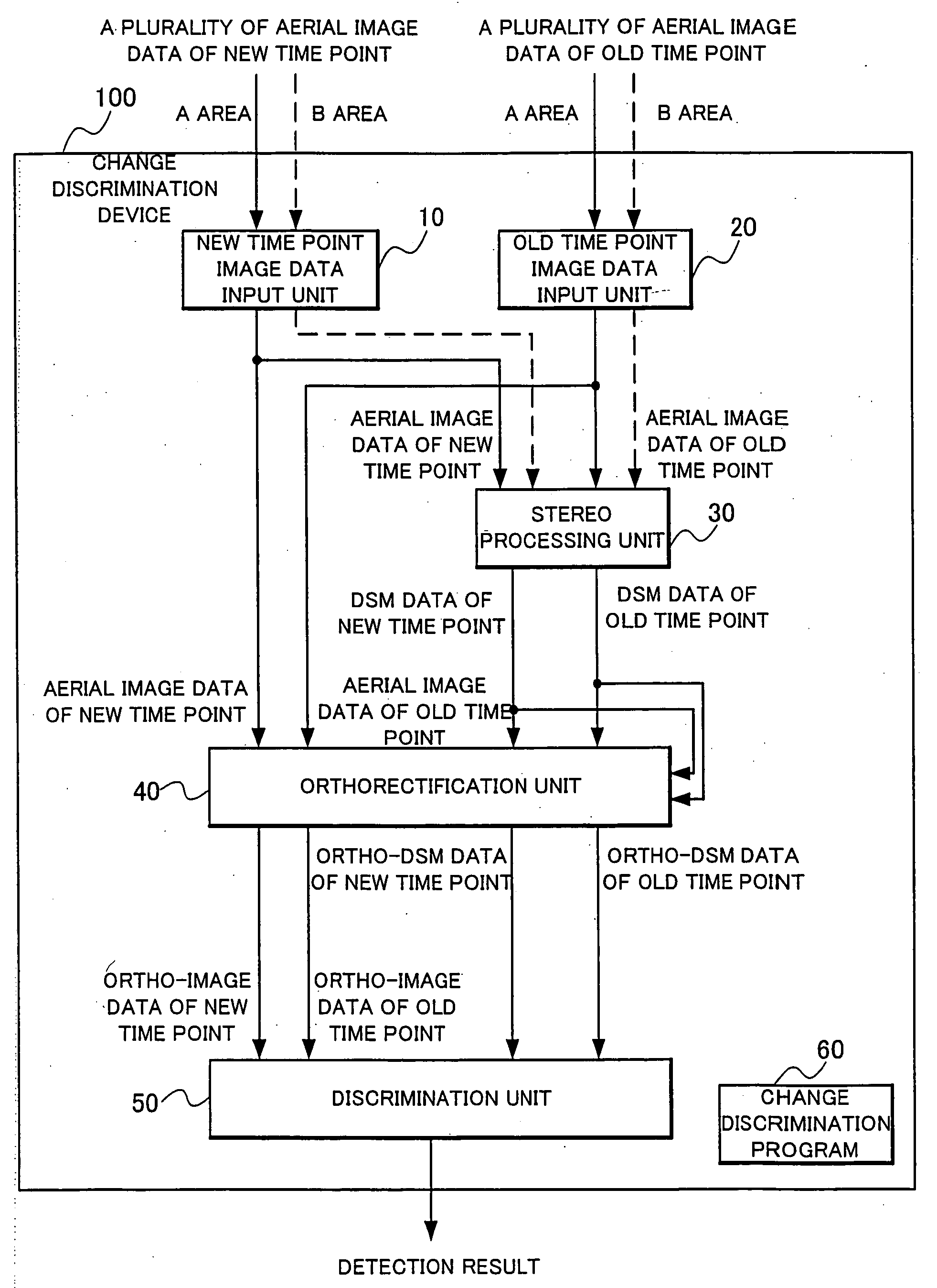
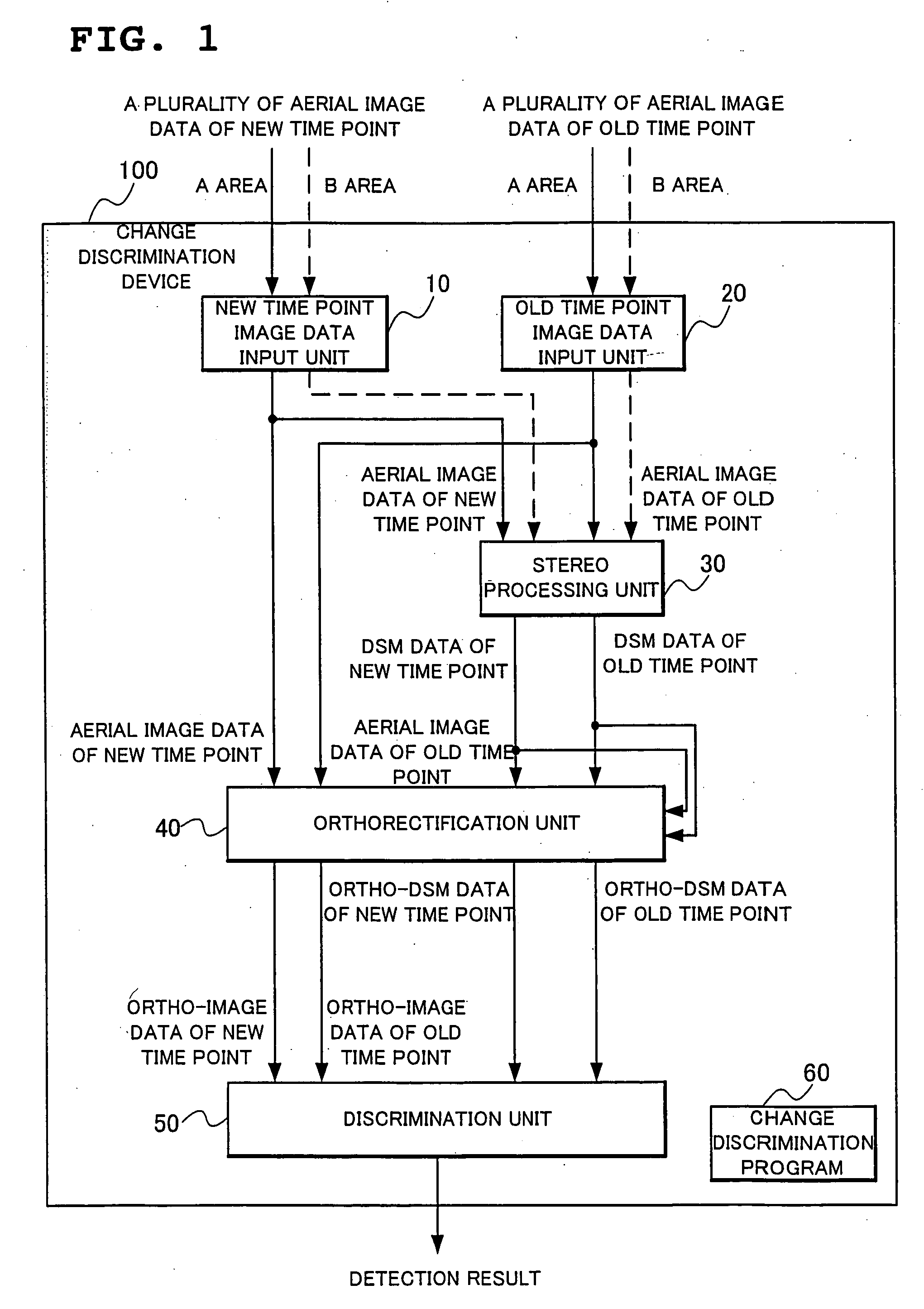
[0084]FIG. 1 is a block diagram showing a structure of a change discrimination device 100 according to the present embodiment.

[0085] With reference to FIG. 1, the change discrimination device 100 according to the present embodiment includes a new time point image data input unit 10, an old time point image data input unit 20, a stereo processing unit 30, an orthorectification unit 40, a discrimination unit 50 and a change discrimination program 60.

[0086] The new time point image input unit 10, which has a function of receiving input of image data of a new time point, receives input of a plurality of pieces of aerial image data obtained by photographing at a new time point.

[0087] The old time point image input unit 20, which has a function of receiving input of image data of an old time point, receives input of a plurality of pieces of aerial image data obtained by photographing at an old time point.

[0088] The stereo processing unit 30, which has a ...

modification example 1

[0226] The modification example 1 is one example of application of the present invention to the change discrimination device shown above as the first embodiment.

[0227] Since the modification example 1 adopts the same basic structure and basic operation as those of the first embodiment, description will be made mainly of a difference from the first embodiment in the following, and description of a structure and operation common to the first embodiment will be appropriately omitted.

[0228] Also as to the respective embodiments and modification examples which will be described later, since they adopt the same basic structure and basic operation as those of the first embodiment similarly to the modification example 1, description will be made mainly of a difference from the first embodiment, and description of a structure and operation common to the first embodiment will be appropriately omitted.

(Contents of Alteration Discriminating Processing in Modification Example 1)

[0229] With ...

modification example 2

[0273] The modification example 2 is to execute alteration discriminating processing by combining a color difference and a height difference.

(Contents of Alteration Discriminating Processing in Modification Example 2)

[0274] With reference to the flow charts in FIG. 15 to FIG. 18, detailed description will be made of pixel extraction processing in the modification example 2 which is applied to Step S403 in FIG. 4 and alteration discriminating processing in the modification example 2 which is applied to Step S404.

[0275] As alterations to be discriminated in the modification example 2, two kinds will be described with respect to “new construction” and “destruction”, respectively.

(New Construction Discriminating Processing)

[0276] With reference to the flow chart shown in FIG. 15, new construction discriminating processing will be detailed.

[0277] In the new construction discriminating processing shown in FIG. 15, a region where a color change and a change of an increase in height...


PUM


Abstract

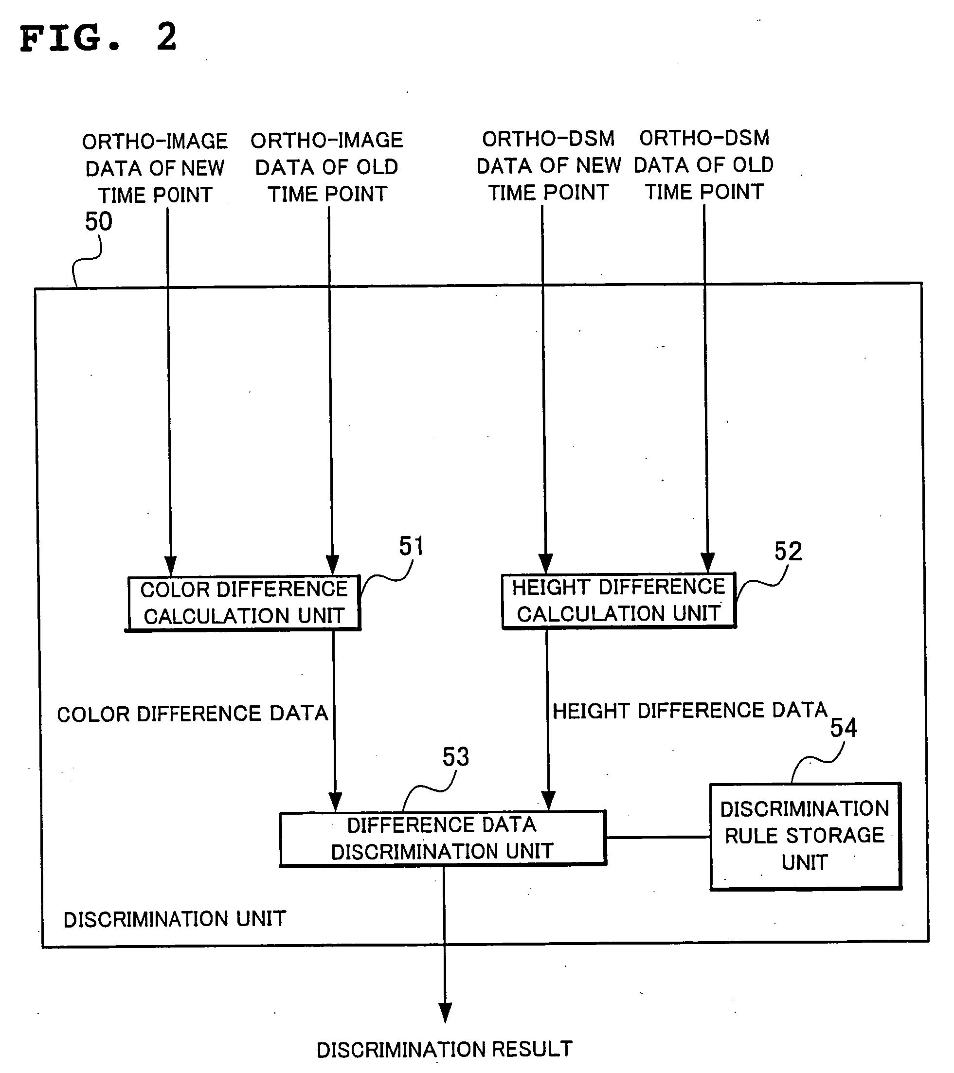
A change discrimination device capable of discriminating an alteration of a photographing target only from an aerial photograph or irrespectively of a difference in lighting conditions or photographing conditions at the time of taking a photo, and at minute distance intervals on a pixel basis, which receives input of a plurality of aerial image data at a new time point and an old time point, generates three-dimensional data (DSM) by subjecting the applied aerial image data to stereo-matching processing, generates ortho-image data and ortho-DSM data by normalizing the aerial image data and the generated DSM data, compares colors by using the generated ortho-image of the new time point and ortho-image of the old time point and compares heights by using the generated ortho-DSM data of the new time point and ortho-DSM data of the old time point to discriminate an alteration of a feature on the earth.

Description

BACKGROUND OF THE INVENTION [0001] 1. Field of the Invention [0002] The present invention relates to a change discrimination device which detects and discriminates a change of a target including a feature on the earth, and more particularly, to a change discrimination device, a change discrimination method and a change discrimination program for detecting and discriminating a change of targets including features on the earth such as houses, structures, vehicles, roads, grounds and forests. [0003] 2. Description of the Related Art [0004] Discrimination of a change (alteration) of a feature on the earth is required for grasping a state of a geographical change and a land use state. Features on the earth here include all, natural or artificial, objects on the earth such as grounds, forests, houses, structures, roads and vehicles. Although in the following, description will be made of discrimination of a change (alteration) of structures including houses, warehouses, factories and schoo...

Claims


Application Information

Patent Timeline
Patent Type & Authority Applications(United States)
IPC IPC(8): G06K9/00G06V20/13
CPCG06K9/0063G01C11/06G06V20/13
Inventor KOIZUMI, HIROKAZUKUNIEDA, KAZUOHASHIZUME, KAZUAKI
Owner NEC SOLUTION INNOVATORS LTD
Learn More