Optimizing power settings in a communication system to mitigate interference

a communication system and power setting technology, applied in the field of interference in a wireless cellular communication system, can solve the problems of large number of small underlay cells within a single macro-cell, interference, introduction of underlaying cells, etc., to achieve optimal power levels, improve and/or facilitate operation in a cellular communication system, and reduce interference

Inactive Publication Date: 2011-11-01
GOOGLE TECHNOLOGY HOLDINGS LLC
View PDF11 Cites 22 Cited by
  • Summary
  • Abstract
  • Description
  • Claims
  • Application Information

AI Technical Summary

Benefits of technology

[0011]The invention may allow improved and / or facilitated operation in a cellular communication system with macro cells and underlay cells and may in particular allow reduced interference in such a communication system. In particular, the invention may provide a dynamic and improved technique to provide unilateral action on the part of residential access points to achieve optimal power levels for mitigating interference.

Problems solved by technology

A widespread introduction of such a system would result in a very large number of small underlay cells within a single macro-cell.
However, a problem arises in the introduction of underlaying cells, such as residential deployments of femto-cells where the deployment process is incremental, unilateral, and ad hoc.
Under these circumstances and without coordination between the RNC of the macro layer and the RAP layer, and considering a much smaller dynamic range of power control at the RAP, there are cases where the RAP suffers interference from macro layer user equipment (UE) in close proximity thereto and vice versa.
In the case of inbound interference case to the RAP from the Macro system the RAP suffers problematic noise rises and the only way out of these difficulties is to turn up its power which can, according to specific scenario, cause two subsequent effects; a) a coverage hole in the macro environment due to RAP power spillover that macro UEs may not be able to camp on themselves, and b) cause so much noise rise (if many RAPs are in the vicinity and there are many connected RAP-UEs) at the Macro node-B site that the macro environment becomes unstable itself (i.e. there is a net reduction in macro capacity).
No settings, regardless of how optimal, are stable for long, and will change over time.
There are many traditional inter-frequency and power control algorithms defined in the art, however these solution require some amount of coordination or control between the hierarchical layers of the communication system.

Method used


Image

  • Optimizing power settings in a communication system to mitigate interference
  • Optimizing power settings in a communication system to mitigate interference
  • Optimizing power settings in a communication system to mitigate interference

Examples


Embodiment Construction

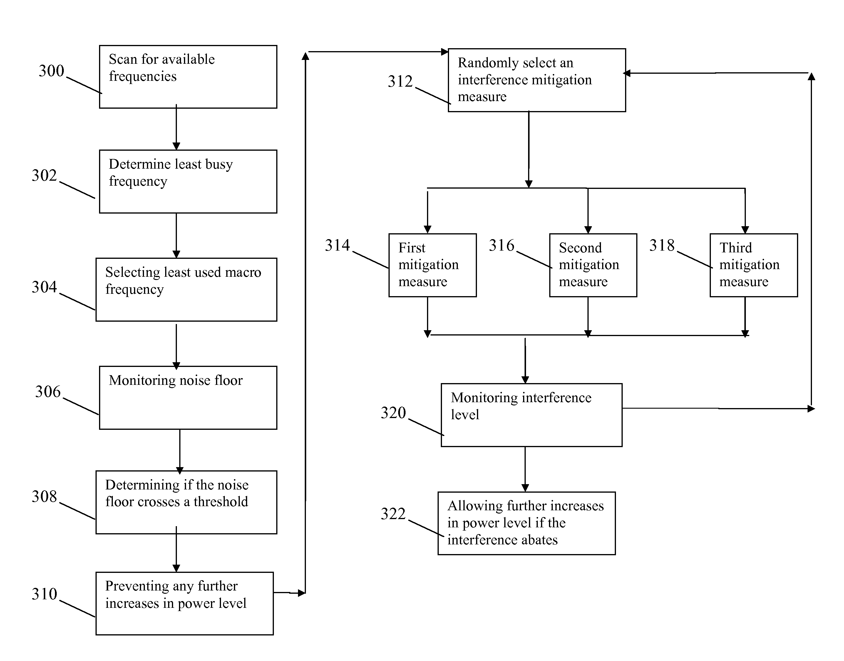
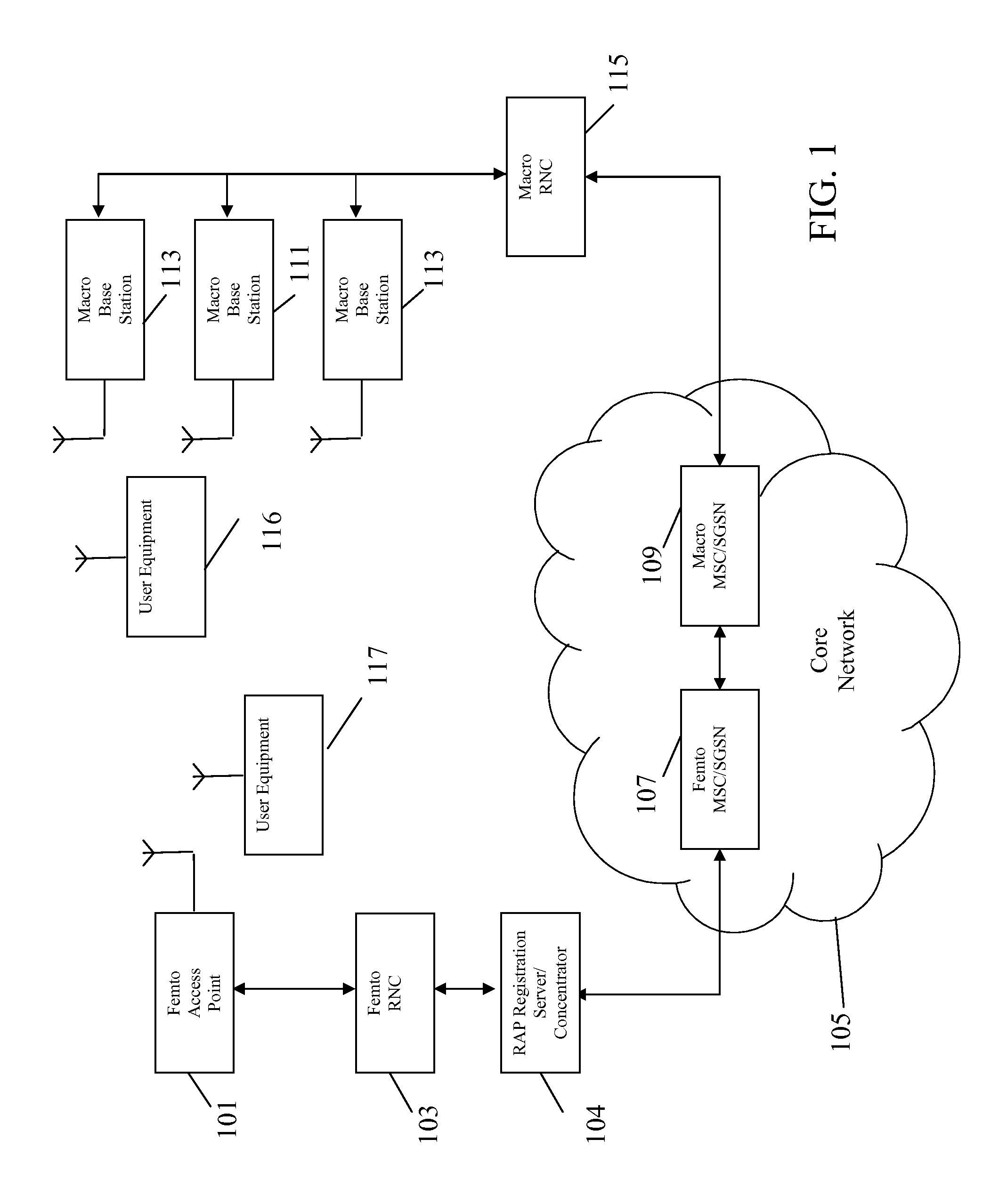
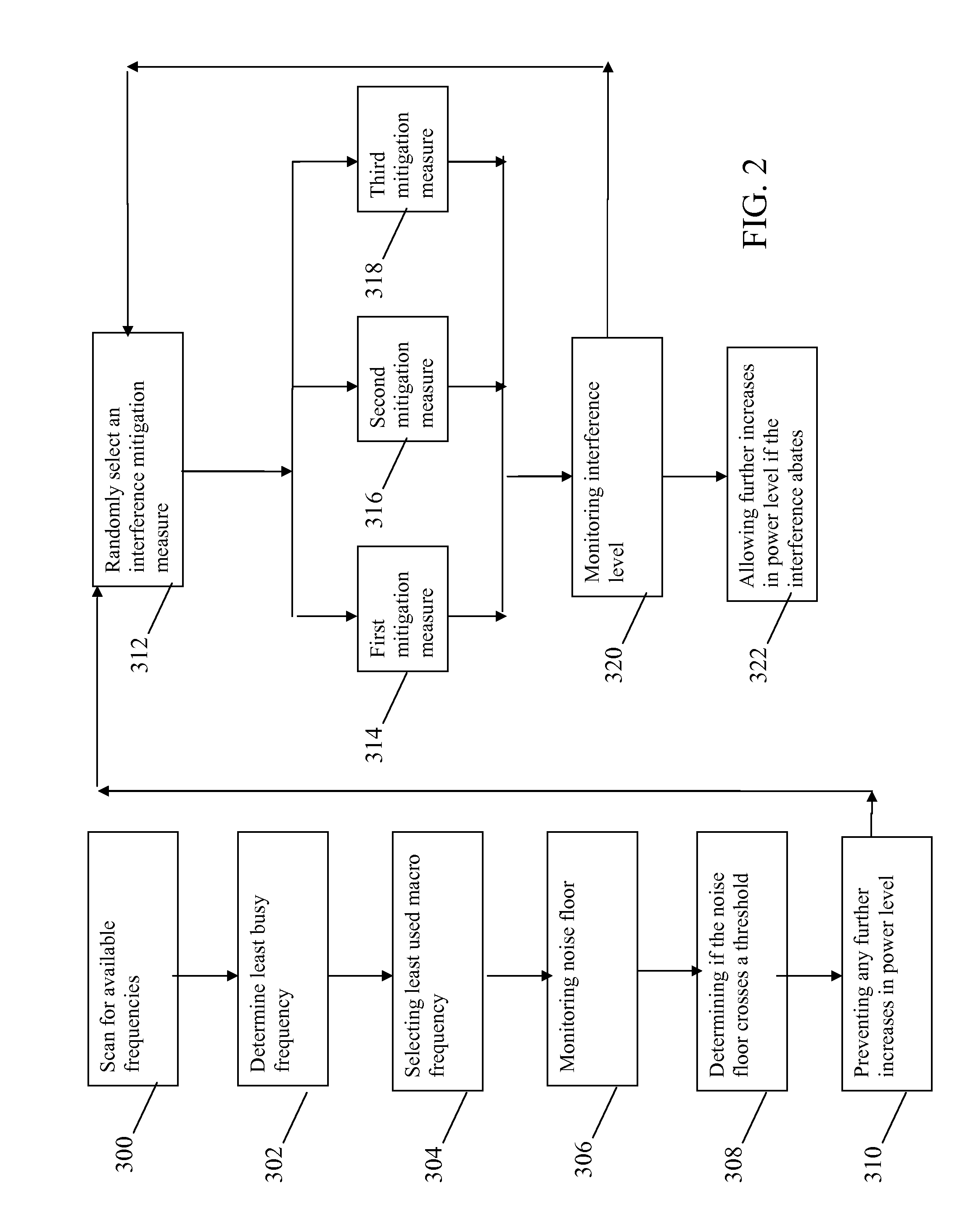
[0018]The following description focuses on embodiments of the invention applicable to a CDMA cellular communication system and in particular to a 3rd Generation Cellular communication system such as a UMTS System. However, it will be appreciated that the invention is not limited to this application but may be applied to many other cellular communication systems. Also, the description will focus on scenarios of a serving access point of a femto-cell. However, it will be appreciated that the described principles apply equally to other hierarchical scenarios.

[0019]FIG. 1 illustrates an example of a cellular communication system which in the specific example is a UMTS cellular communication system. In the system, a macro-layer is formed by macro-cells supported by base stations. Furthermore, an underlay layer of pico-cells or femto-cells are supported by a large number of small base stations which henceforth will also be referred to as access points. Specifically, each access point may ...


PUM


Abstract

A method includes a first step of monitoring a noise floor. A next step includes determining if the noise floor crosses a threshold level. A next step includes preventing any further increases in a Common Pilot Channel power level. A next step includes randomly selecting and performing an interference mitigation measure. A next step includes monitoring an interference level. A next step allows further increases in a Common Pilot Channel power level if the interference abates by more than a predetermined amount.

Description

FIELD OF THE INVENTION[0001]The invention relates to interference in a wireless cellular communication system and in particular, but not exclusively, to power settings of cells in a multi-layer cellular communication system.BACKGROUND OF THE INVENTION[0002]A method which has been used to increase the capacity of cellular communication systems is the concept of hierarchical cells wherein a macro-cell layer is underlayed by a layer of typically smaller cells having coverage areas within the coverage area of the macro-cell. In this way, smaller cells, known as micro-cells, pico-cells, or femto-cells, are located within the same coverage area as larger macro cells. The pico-cells and femto-cells have much smaller coverage thereby allowing a much closer reuse of resources. Frequently, the macro-cells are used to provide coverage over a large area, and the smaller underlay cells are used to provide additional capacity in densely populated areas and hotspots, for example. Furthermore, femt...

Claims


Application Information

Patent Timeline
Patent Type & Authority Patents(United States)
IPC IPC(8): H04B15/00H04W36/00H04B7/00H04W40/00
CPCH04W52/243H04W52/325
Inventor FOSTER, GERARD T.BHATOOLAUL, DAVID LAHIRI L.FREIBERG, LORENZ F.HEYWOOD, RICHARD
Owner GOOGLE TECHNOLOGY HOLDINGS LLC
Why Eureka
Try Eureka