Wireless communication for vehicle based node

a node and wireless communication technology, applied in the field of vehicle-based nodes, can solve the problems of difficult to provide high data rate support for fast moving vehicles, particularly difficult for a communication infrastructure to support mobility, and the general mobility support tends to be relatively slow

Active Publication Date: 2022-07-05
BLUWIRELESS TECH
View PDF11 Cites 0 Cited by
  • Summary
  • Abstract
  • Description
  • Claims
  • Application Information

AI Technical Summary

Benefits of technology

[0015]The invention may provide improved and / or facilitated operation and / or improved performance for a beamform based mm wave radio communication system supporting (potentially fast) moving vehicles. The approach may, in particular, provide efficient and reliable communication and may in many embodiments provide improved capacity of the available air interface resource supporting communication for a vehicle. The approach may in many embodiments provide improved consistency and reduced data interruption and / or performance degradation.
[0016]The approach may in particular provide increased capacity for the air interface and may specifically be suitable for providing increased capacity for hot spots. The approach may allow efficient and / or improved load balancing in many embodiments. Further, in many embodiments, the approach may allow efficient operation without requiring high complexity of operation or functionality. The approach may in particular provide advantageous performance by allowing wireless modems to only be able to search for a beacon signal in a single channel for extended periods of time.
[0017]The approach may allow load balancing and resource management to be performed based on wireless modem operations and functionality and with reduced requirements for functionality in the access points or fixed network. In particular, efficient resource management, such as improved load balancing, may typically be achieved without a complex resource management function being implemented in the fixed network or access system (including access points).
[0018]The approach may provide a more flexible approach in many scenarios. It may in many systems allow facilitated introduction of new functionality or additional air interface capacity. It may for example facilitate introduction of an additional access point to provide increased air interface capacity for a hot spot area.
[0019]The use of beams from directional antennas may specifically support radio communication links from different wireless modems of the vehicle to the same access point or to different access points. It may allow steering of the beams towards the same or different access points thereby enabling or improving multiple links between the vehicle and access points. This may provide improved performance.

Problems solved by technology

A particularly difficult challenge for a communication infrastructure is to support mobility.
In particular, it is difficult to provide high data rate support for fast moving vehicles, for example in order to support high capacity Internet access on board trains.
However, the handovers and general mobility support tend to be relatively slow (with an interruption in data connectivity) and relatively complex and tend to not be suitable for faster moving mobile stations, such as fast-moving vehicles.
Traditional Wi-Fi access points also tend to be limited to a relatively low capacity / throughput.
However, such systems tend to have large cells and to be restricted to much lower capacity and throughput speed than desired.
A general problem is that in order to support high capacity communication with, in particular, a fast moving vehicle, a significant amount of air interface resource (spectrum) is required, and this tends to restrict the capacity that can be provided by many existing systems in the most frequently used frequency ranges.
However, the mobility challenges known from e.g. Wi-Fi systems become even more significant.
For a fast moving vehicle this results in an increased number of handovers and in continuously fast changing conditions.
Whilst some direction changes can be accommodated by steering the antennae of the radio communication link, there is not the omnidirectional capability of typical cellular and Wi-Fi radios.
In general, the efficient usage of the air interface in mm wave communication and with potentially fast-moving vehicles is a difficult challenge to address.
However, most approaches for supporting communication for in particular fast moving vehicles tend to be suboptimal.
In particular, providing sufficient air interface capacity to support high rate communication with moving vehicles, such as for supporting Internet access to a high number of passengers on a train, is a difficult challenge.
It is in particular difficult for mm wave communication systems as the particular propagation properties thereof tend to make it inefficient to merely reduce cell sizes and increase the number of access points.
It is further difficult to achieve for systems where the vehicle based communications have limited functionality and therefore limited information.
For example, such communication functions may not be able to continuously and simultaneously detect, measure, and evaluate all possible candidate access points.
Indeed, many approaches for such systems tend to result in significant hotspots, uneven load balancing, and a less than optimum practical usage of the potentially available air interface resource and capacity.
Further, efficient resource management and load balancing for the air interface tend to require complex and centralized resource management functions that are based on information provided for several access points.
This tends to increase complexity and overheads (e.g. due to signaling) and is not optimal for systems that seek to provide more control to remote stations.
It also tends to be less suitable for updating and introduction of the new functions and operations to existing systems.

Method used


Image

  • Wireless communication for vehicle based node
  • Wireless communication for vehicle based node
  • Wireless communication for vehicle based node

Examples


Embodiment Construction

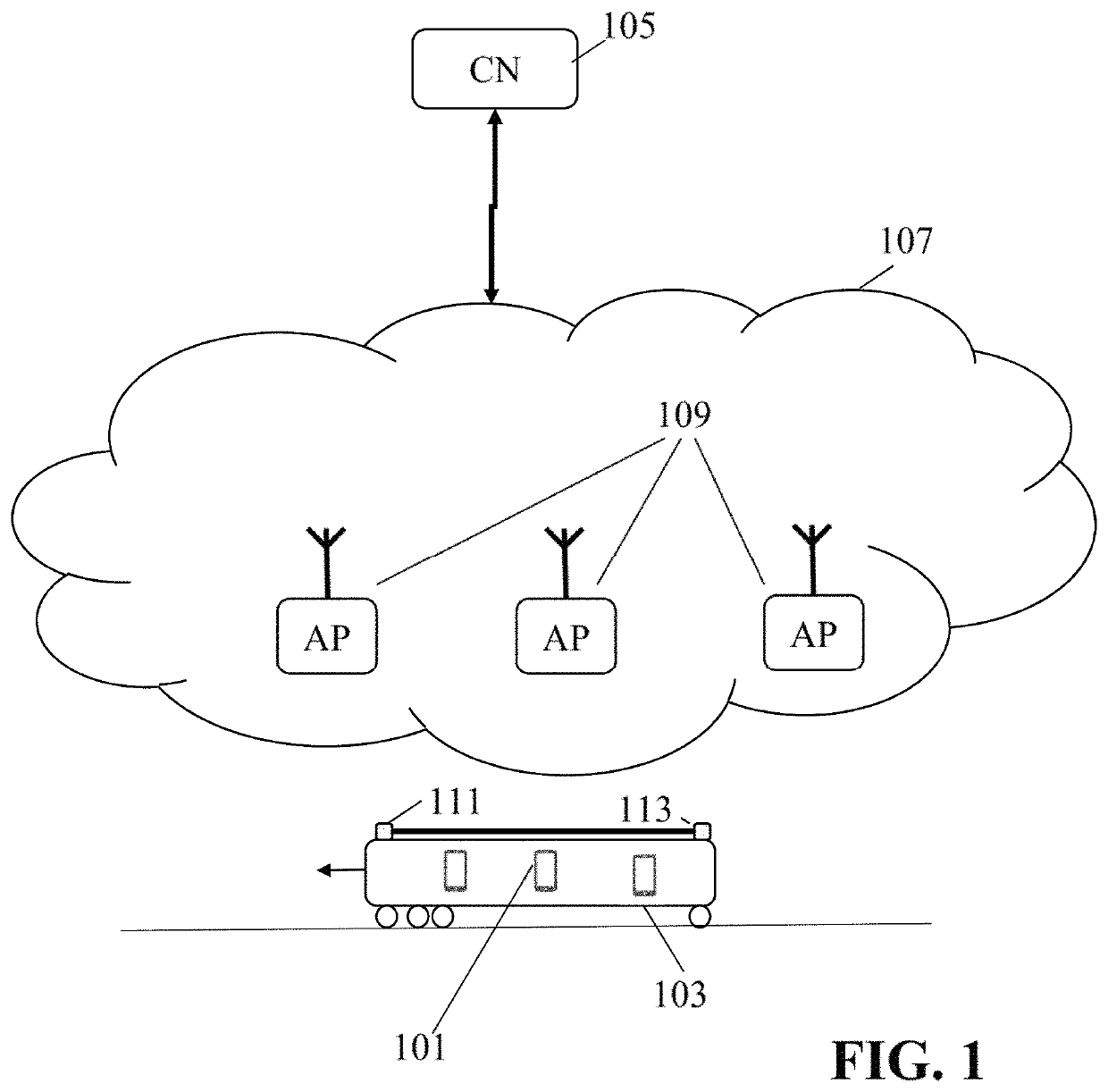
[0059]FIG. 1 illustrates an example of elements of a communication system which supports communication with end nodes that are located in moving vehicles, and in particular in fast moving vehicles such as cars, boats, buses, and trains. The following description will focus on an example in which the vehicle is a train, but it will be appreciated that in other embodiments the end node may be part of other vehicles, such as e.g. a bus driving on a motorway.

[0060]In the example of FIG. 1, a communication / data session is established between a correspondent node 105 and an end node 101 located in a train / vehicle 103. It will be appreciated that references to an entity being at / with / in / on etc. a vehicle includes any physical or logical form of the vehicle and entity being substantially co-moving, including the entity being positioned on, attached to, embedded within, etc. the vehicle. It will also be appreciated that it does not require the entity to be immovable with respect to the vehic...


PUM


Abstract

A communication system comprises a fixed network comprising access points for mm wave radio communication using directional beams. A wireless modem of a vehicle comprises a first search circuit searching for a beacon transmission in a first frequency channel. A first data receiver extracts data from a detected beacon signal including: an indication of a first access point transmitting the beacon signal; a first load value indicative of a loading of the first access point; and an indication of a second access point having overlapping coverage with the first access point. Another receiver extracts data from a second beacon signal transmitted by the second access point in a second frequency channel including a second load value indicative of a loading of the second access point. A controller selects a target access point dependent on the first and second load values, and initializes a link setup with the target access point.

Description

FIELD OF THE INVENTION[0001]The invention relates to support of communication with a vehicle based node, and in particular, but not exclusively, to wireless communication for a node on a train.BACKGROUND OF THE INVENTION[0002]Wireless communication has become ubiquitous and forms the basis of many applications and services provided to the consumer of today. A particularly widespread set of wireless communication systems, colloquially known as Wi-Fi, has been developed by the Wi-Fi Alliance and is standardized in the Institute of Electrical and Electronics Engineers' (IEEE) 802.11 standards. Wi-Fi wireless communication systems are typically used to implement Wireless Local Area Networks (WLANs) in many different environments, such as in homes, workplaces, or public areas.[0003]Wi-Fi systems provide many functions, features and services suitable for efficient implementation of WLANs and data communication. The IEEE 802.11 standards have been, and are being, developed to provide an in...

Claims


Application Information

Patent Timeline
Patent Type & Authority Patents(United States)
IPC IPC(8): H04W48/16H04W72/04H04W88/06H04B7/08H04W88/08
CPCH04W48/16H04B7/0897H04W72/046H04W88/08H04W48/20H04W84/005
Inventor LEGG, PETER JONATHONPASCOE, JAMES SIMONDAVIES, SIMON
Owner BLUWIRELESS TECH
Why Eureka
Try Eureka