Generation of image for an autostereoscopic display

an autostereoscopic display and image technology, applied in the field of autostereoscopic display generation, can solve the problems of increasing image degradation, affecting the performance of autostereoscopic displays, and reducing the dynamic trade-off, so as to improve the dynamic trade-off, improve the performance, and mitigate undesirable effects

Active Publication Date: 2020-04-28
KONINKLJIJKE PHILIPS NV
View PDF15 Cites 0 Cited by
  • Summary
  • Abstract
  • Description
  • Claims
  • Application Information

AI Technical Summary

Benefits of technology

[0021]The invention may provide an improved three dimensional image from an autostereoscopic display. In particular, it may in many applications provide improved perceived image quality and / or an improved 3D effect for one or more viewers. The approach may provide an improved user experience in many scenarios. The approach may in particular provide an improved dynamic trade-off between blur, 3D effect and risk of stereo inversion.
[0063]This may provide improved and / or facilitated operation in many embodiments. The invention may in many applications provide improved rendering of a three dimensional image on an autostereoscopic display.

Problems solved by technology

However, as this is relatively inconvenient to the user, it is in many scenarios desirable to use autostereoscopic displays that directly generate different views and projects them to the eyes of the user.
Thus, autostereoscopic displays typically do not spread the views over the entire possible viewing or projection angle.
However, the representation of different views provides additional complications and potential image degradations.
However, as the plurality of views are typically generated from input data representing the central view(s), the image degradation increases for the outer views for which an increased disparity and thus position shifting from the original image is required.
Accordingly, as a user moves towards the extreme views at the edges of a viewing cone, a quality degradation is often perceived.
However, the image quality is reduced towards the sides.
A particular problem when displaying three dimensional images is that cross-talk may occur between different views.
For autostereoscopic displays, cross-talk is typically a significant issue due to the light from individual (sub-)pixels having a relatively large dissemination area.
Thus, due to cross-correlation between different views (with different disparities and thus with some depth objects being at different positions), a blurring effect may in practice occur which results in a loss of the sharpness of the image.
Another issue is that due to the limited viewing angle of a viewing cone, it is possible that a viewer may not be fully positioned within a viewing cone but may for example have one eye in one viewing cone and another eye in a neighbor viewing cone as exemplified in FIG. 4.
However, this may result in a stereo inversion wherein the right eye receives an image generated for the left eye and the left eye receives the image generated for the right eye.
Thus, as a viewer moves towards the end of a view cone and passes into the neighbor view cone with one eye, a stereo inversion occurs which is perceived as very disturbing and uncomfortable to the user.
However, although this approach may mitigate stereo inversion it also has some disadvantages.
Most significantly, it reduces the viewing range within each viewing cone in which the full three dimensional effect is perceived, i.e. it reduces the sweet spot.

Method used


Image

  • Generation of image for an autostereoscopic display
  • Generation of image for an autostereoscopic display
  • Generation of image for an autostereoscopic display

Examples


Embodiment Construction

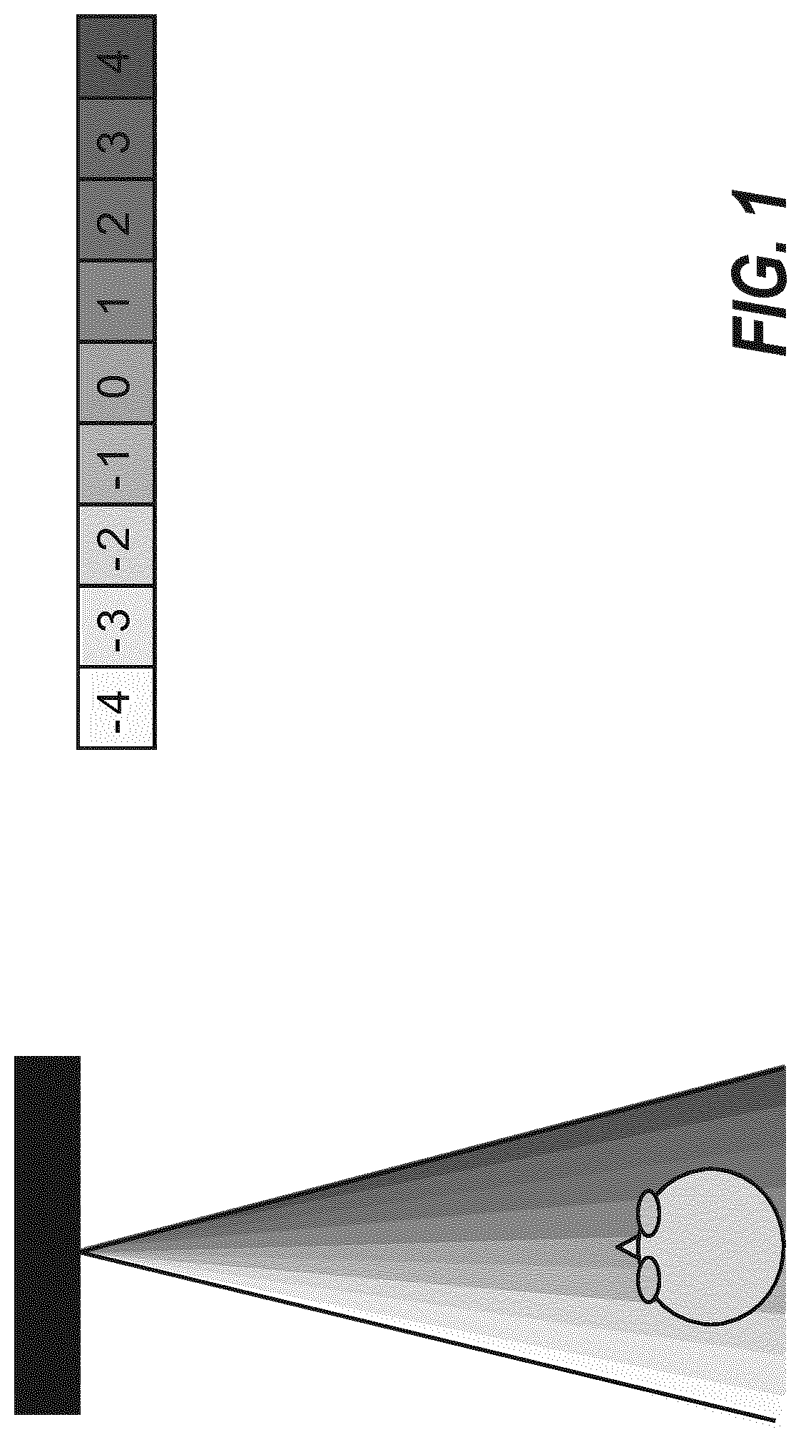
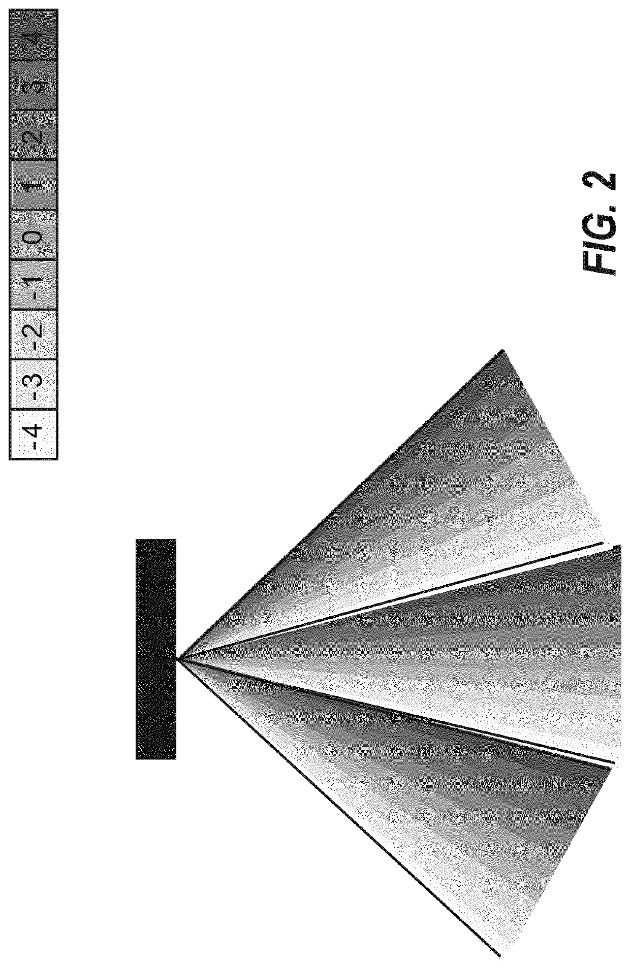
[0079]The autostereoscopic display arrangement 501 of FIGS. 5 and 6 comprises a display panel 503. The display arrangement 501 may contain a light source 507, e.g., when the display is an LCD type display, but this is not necessary, e.g., for OLED type displays.

[0080]The display panel 503 comprises a large number of pixels which can be individually driven to provide a given light output. In some embodiments, the light output may be controlled by the display panel 503 modulating (typically attenuating) a light source (such as an LCD panel modulating a backlight (which itself may be variable). In other embodiments, the individual pixel of the display panel 503 may be a light generating and radiating element which itself generates the light.

[0081]A pixel may be any addressable element of the display panel 503 which can be used to vary the light output from the display. As such the term pixel may also refer to light varying or controlling elements that only affect e.g. one color channel...


PUM


Abstract

A display image for a display panel (503) of an autostereoscopic display projecting the display image in a plurality of view cones is generated. A source (803) provides a three dimensional representation of a scene to be displayed and a generator (805) generates the display image from the representation. For each pixel, the generator (805) determines a scene viewpoint direction indication reflecting a view point direction for the scene in response to a direction mapping function and a view cone projection direction indication reflecting a projection direction for the pixel within the view cones. The direction mapping function reflects a relationship between view cone projection directions and scene view point directions. The pixel value corresponding to the view point direction is then generated from the three dimensional representation. In addition, a processor (809) determines a viewer characteristic; and an adapter (811) for adapts the direction mapping function in response to the viewer characteristic.

Description

CROSS-REFERENCE TO PRIOR APPLICATIONS[0001]This application is the U.S. National Phase application under 35 U.S.C. § 371 of International Application No. PCT / EP2016 / 058976, filed on Apr. 22, 2016, which claims the benefit of EP Patent Application No. EP 15166346.5, filed on May 5, 2015. These applications are hereby incorporated by reference herein.FIELD OF THE INVENTION[0002]The invention relates to generation of an image for an autostereoscopic display, and in particular, to generation of a display image for a display panel of an autostereoscopic display from an input three dimensional image.BACKGROUND OF THE INVENTION[0003]Three dimensional displays are receiving increasing interest, and significant research in how to provide three dimensional perception to a viewer is being undertaken. Three dimensional displays add a third dimension to the viewing experience by providing a viewer's two eyes with different views of the scene being watched. This can be achieved by having the user...

Claims


Application Information

Patent Timeline
Patent Type & Authority Patents(United States)
IPC IPC(8): H04N13/279H04N13/366H04N13/376H04N13/351H04N13/349H04N13/305H04N13/302H04N13/368H04N13/125H04N13/128
CPCH04N13/279H04N13/349H04N13/376H04N13/366H04N13/302H04N13/351H04N13/305H04N13/368H04N13/125H04N13/128G09G5/00
Inventor KROON, BART
Owner KONINKLJIJKE PHILIPS NV
Why Eureka
Try Eureka