Kinematical joints for x-ray systems

a technology of kinematic joints and x-ray systems, applied in the field of generating xray images, can solve the problems of cumbersome operation, limited rotation range, and relatively bulky c-arcs, and achieve the effect of facilitating operation, reducing the effort to ensure the correct angularity of all components during operation, and simplifying control of angulation rotation

Active Publication Date: 2020-07-30
KONINKLJIJKE PHILIPS NV
View PDF31 Cites 0 Cited by
  • Summary
  • Abstract
  • Description
  • Claims
  • Application Information

AI Technical Summary

Benefits of technology

[0039]According to an example, the method, in step b), the moving comprises a moving of the pivoting point C along a circular path The angulation range can thus be extended further.
[0040]According to an aspect, the invention provides an improved construction for interventional X-ray imaging systems. As an advantage, a simplified control of the angulation rotation around an Iso-centre is provided. The beams are coupled in a way that the detector and the receptor are guided in a parallelogram guidance around the object to be irradiated. A transmission mechanism in the image chain provides an easy transmission. Hence, the synchronisation is provided and the effort for ensuring the correct angular of all components during operation is reduced. The operation is thus facilitated.

Problems solved by technology

However, C-arcs may be relatively bulky, for instance when not in use, or they can be relatively heavy, requiring accordingly motorized movement support.
Furthermore, rotation range may be limited due to size and complexity of the supporting arrangement.
However, it has been shown that the operation, especially the control may be cumbersome and a synchronization of all components for an angulation rotation may require some effort.

Method used


Image

  • Kinematical joints for x-ray systems
  • Kinematical joints for x-ray systems
  • Kinematical joints for x-ray systems

Examples


Embodiment Construction

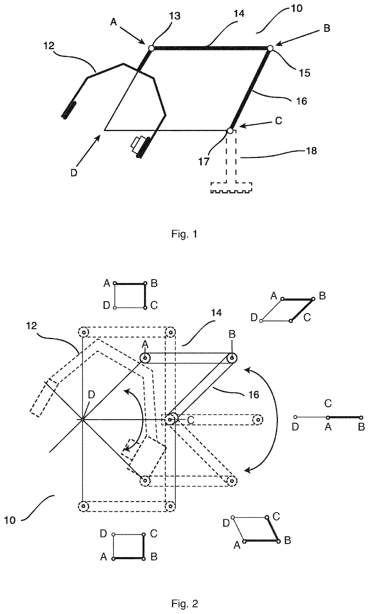
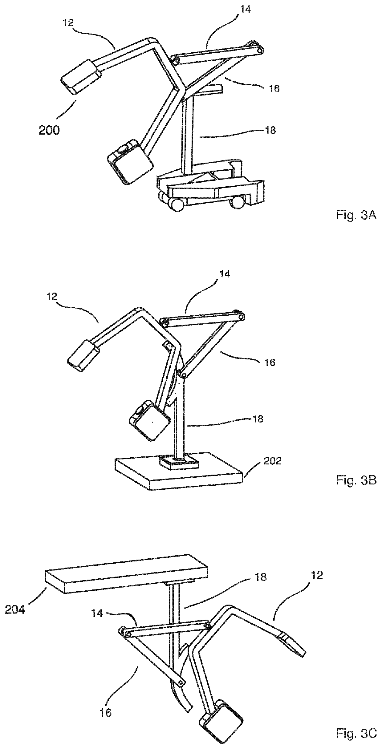
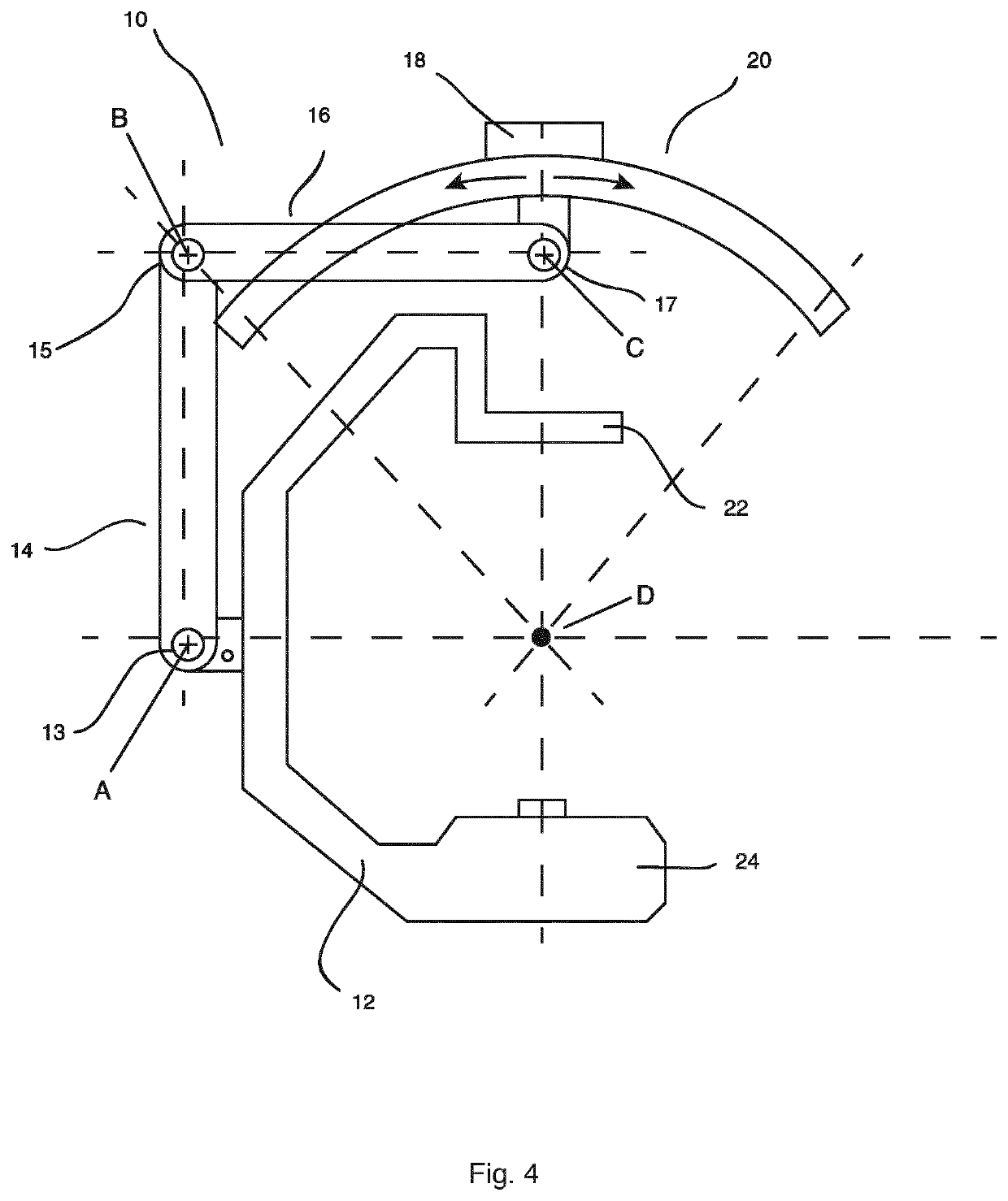
[0051]FIG. 1 shows an imaging support arrangement 10 for generating an X-ray image. The imaging support arrangement 10 for generating an X-ray image comprises a support structure 12, a primary supporting beam 14, a secondary supporting beam 16, a mounting arrangement 18, wherein the support structure 14 is configured to hold an image detector 22 at a first end and an X-ray source 24 at a second end with a connection line in between, on which an Iso-centre D can be located. The support structure 12 is connected to the primary supporting beam 14 in a first pivotable connection point A with a first connector 13, and the primary supporting beam 14 is connected to the secondary supporting beam 16 in a second pivotable connection point B with a second connector 15, and the secondary supporting beam 14 is connected to the mounting arrangement 18 in a third pivotable connection point C with a third connector 17. The first, second and third pivotable connection points (A, B, C) and the Iso-c...


PUM


Abstract

The present invention relates to an imaging support arrangement (10), a system (50) and a method (100) for generating an X-ray image. In order to generate an X-ray image am imaging support arrangement (10) for generating an X-ray image is provided. The imaging support arrangement (10) for generating an X-ray image comprises a support structure (12), a primary supporting beam (14), a secondary supporting beam (16), a mounting arrangement (18), wherein the support structure (14) is configured to hold an image detector (22) at a first end and an X-ray source (24) at a second end with a connection line in between, on which an Iso-centre D can be located. The support structure (12) is connected to the primary supporting beam (14) in a first pivotable connection point A, and the primary supporting beam (14) is connected to the secondary supporting beam (16) in a second pivotable connection point B, and the secondary supporting beam (16) is connected to the mounting arrangement (18) in a third pivotable connection point C. The first, second and third pivotable connection points (A, B, C) and the Iso-centre D define a parallelogram. As a result, a parallelogram guidance is realized.

Description

FIELD OF THE INVENTION[0001]The present invention relates to generating X-ray images, and relates, in particular, to an imaging support arrangement for generating an X-ray image, an X-ray imaging system for generating X-ray images and a method for generating X-ray images.BACKGROUND OF THE INVENTION[0002]To suspend an X-ray source and a detector of an X-ray system, C-arc shaped structures may be used. As an example, a C-arc is used to realize a rotational movement, in particular, an orbital or angulation rotation of the imaging devices, i.e. detector and source, around an object to be irradiated. The rotation may be required during an intervention to acquire e.g. 2D images from different projection directions, or also to provide a plurality of image slices for a 3D reconstruction from multiple images. However, C-arcs may be relatively bulky, for instance when not in use, or they can be relatively heavy, requiring accordingly motorized movement support. Furthermore, rotation range may...

Claims


Application Information

Patent Timeline
Patent Type & Authority Applications(United States)
IPC IPC(8): A61B6/00
CPCA61B6/4458A61B6/4476A61B6/4464A61B6/4441A61B6/4405A61B6/4429A61B6/4435A61B6/4482
Inventor DE BOER, JACOB
Owner KONINKLJIJKE PHILIPS NV
Why Eureka
Try Eureka