Method and apparatus for securing a movable item to a structure

a technology of moving objects and electronic locks, applied in the field of electronic locks for securing movable objects to structures, can solve the problems of malicious persons, vandalism of stations, and selective unsealing of bicycles by users

Active Publication Date: 2011-11-22
SOC DE VELO & LIBRE SERVICE
View PDF32 Cites 35 Cited by
  • Summary
  • Abstract
  • Description
  • Claims
  • Application Information

AI Technical Summary

Problems solved by technology

A user may selectively unsecure and secure again the bicycle from the bicycle rack in certain circumstances, for instance after paying a given fee and / or providing a personal identification code.
Such rental systems generally comprise a plurality of rental stations located in different public locations, making them likely targets of acts of vandalism from malevolent individuals.
Such a station may be subject to vandalism.
Indeed, a malicious person may tug at the bicycle engaged in the renting station, using the latch as a lever and the axle as a pivot point to bend the latch out of shape or damage the keeper and free the bicycle from the renting station without paying the given fee.
However, such systems are still prone to property damage and theft of bicycles and may thus cause great financial harm to operators of such bicycle renting systems.
Moreover, in some bicycle rental systems, unsecuring a bicycle from a bicycle rental station involves lifting the bicycle or otherwise manipulating the bicycle such that a great physical effort is required from a user of the bicycle rental system.
This activity is inconvenient for the user and may lead to injuries.
Furthermore, in some bicycle rental systems, the task of guiding the bicycle towards the bicycle rack for the purpose of securing the bicycle to the bicycle rack may be arduous and inconvenient for a user.

Method used


Image

  • Method and apparatus for securing a movable item to a structure
  • Method and apparatus for securing a movable item to a structure
  • Method and apparatus for securing a movable item to a structure

Examples


Embodiment Construction

[0083]In the following description of the embodiments, references to the accompanying drawings are by way of illustration of an example by which the invention may be practiced. It will be understood that other embodiments may be made without departing from the scope of the invention disclosed.

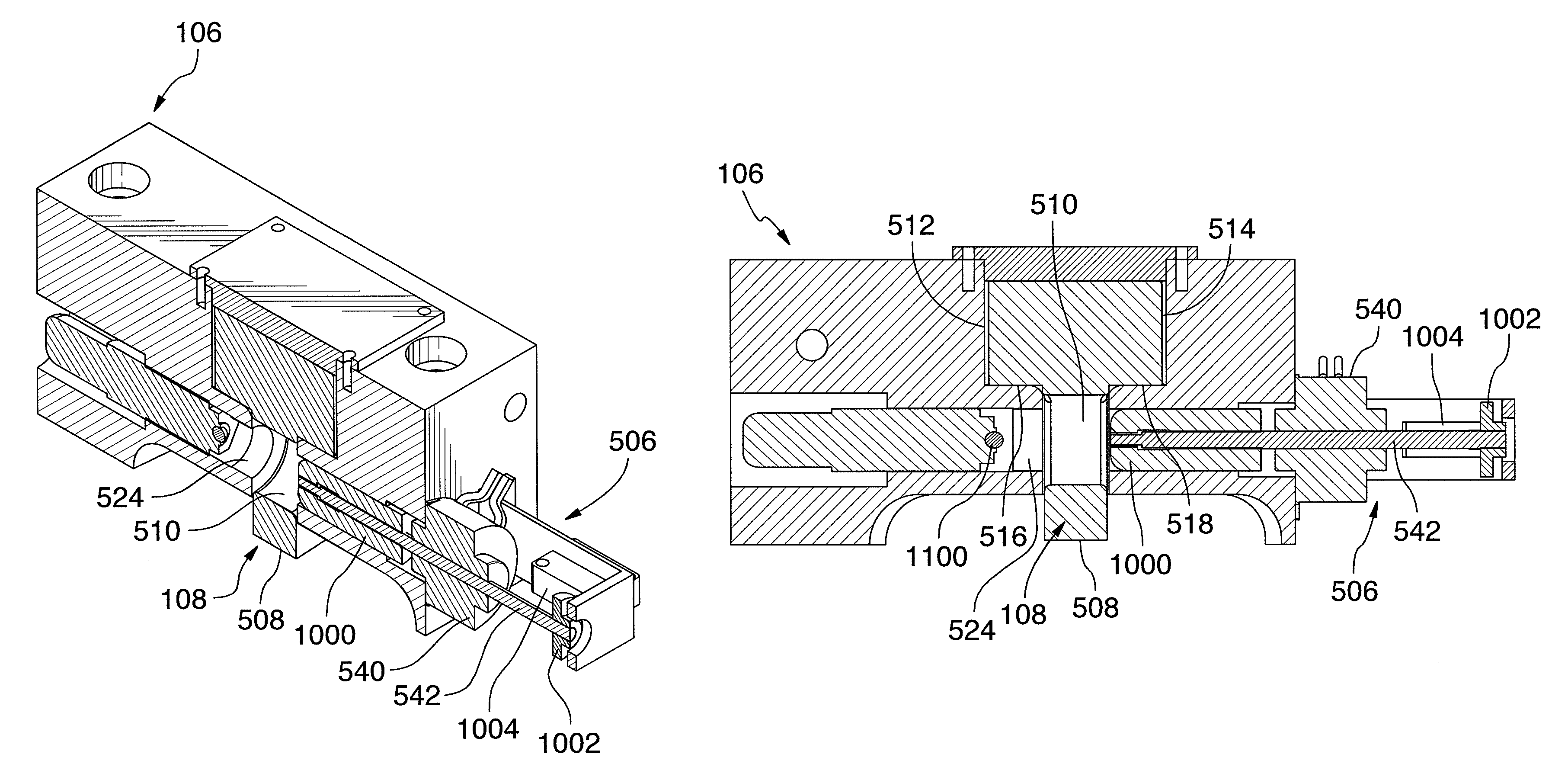
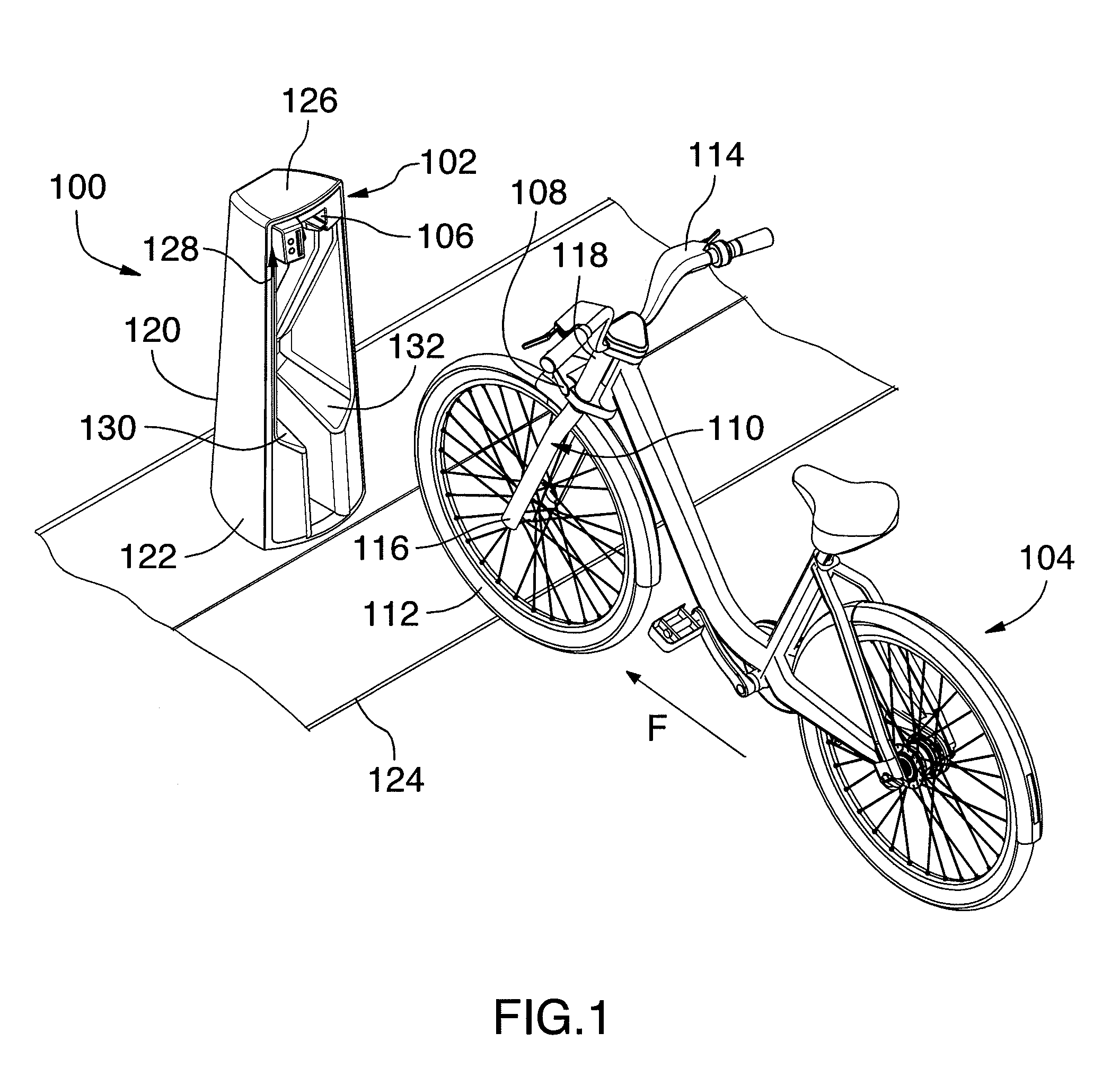
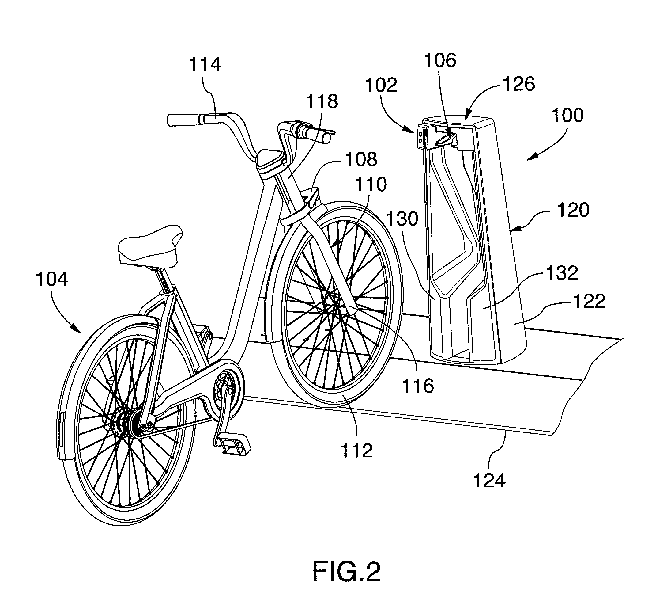
[0084]The invention provides an electronic lock for securing a movable item to a structure. As it will be more clearly understood upon reading of the present description, the electronic lock may advantageously be used in a great variety of applications, such as for example in a vehicle rental system such as a bicycle rental system. The skilled addressee will however appreciate that many other applications may be considered, as it will be more detailed thereinafter.

[0085]In the following description of the illustrated embodiments, the movable item comprises a bicycle and the structure comprises a bicycle rack. The bicycle rack is part of a bicycle renting station and is fixedly mounted thereto. ...


PUM


Abstract

An electronic lock for removably securing a movable item to a structure, the electronic lock comprising first and second complementary cooperating connecting members, each being fixedly mounted to a respective one of the movable item and the structure and being engageable together in a lockable position; and a securing assembly for securing the first and second connecting members together when engaged in the lockable position, the securing assembly comprising a movable locking member operatively associated to the first connecting member, a locking aperture defined in the second connecting member, the locking aperture being adapted for receiving the movable locking member when the connecting members are engaged together in the lockable position; an actuator operatively coupled to the movable locking member for actuating the movable locking member between an unlocked position enabling disengagement of the first and second connecting members and a locked position wherein the movable locking member engages the locking aperture, and electronic control means for controlling selective actuation of the movable locking member.

Description

CROSS REFERENCE TO RELATED APPLICATION[0001]The present application claims priority from U.S. provisional patent application Ser. No. 61 / 047,162 filed Apr. 23, 2008, the specification of which is herein incorporated by reference.FIELD OF THE INVENTION[0002]The invention relates to locking systems. More precisely, the invention pertains to an electronic lock for securing a movable item to a structure and an associated method.BACKGROUND OF THE INVENTION[0003]Securing a moveable item to a structure is of great interest for various applications. For instance, it may be desirable to secure a vehicle to a fixed structure. This may be particularly advantageous in applications where the vehicle is to be rented for a given amount of time.[0004]More specifically, there has been in recent years a rise in the popularity of automated rental systems for vehicles such as bicycles for example. Such a system generally comprises an automated rental station from which a user may rent a bicycle for a g...

Claims


Application Information

Patent Timeline
Patent Type & Authority Patents(United States)
IPC IPC(8): G07F7/00
CPCB62H3/02B62H3/04G07F17/10B62H2003/005Y10T70/5872Y10T70/5876Y10T70/50Y10T70/625Y10T70/7051Y10T70/60Y10T70/5881
Inventor KHAIRALLAH, CHARLES IBRAHIMDALLAIRE, MICHEL
Owner SOC DE VELO & LIBRE SERVICE
Why Eureka
Try Eureka