Hair styling device

a hair styling and heat dissipation technology, applied in the direction of curling irons, hair equipments, curling-tongs, etc., can solve the problems of inferior sliding properties of hairs between contact surfaces, unpleasant tension of users at hair lines, and upper limit of tensile force, so as to prevent excessive tension at the hair line of users, facilitate contact surfaces, and prevent excessive hair damage

Inactive Publication Date: 2011-11-29
BRAUN GMBH
View PDF25 Cites 6 Cited by
  • Summary
  • Abstract
  • Description
  • Claims
  • Application Information

AI Technical Summary

Benefits of technology

A hair styling device according to the invention, includes contact surfaces that are at least regionally provided with an enamel layer. The enamel creates a very gentle contact surface for the hairs. Excessive damage to the hairs to be styled due to mechanical stress, as well as excessive tension at the hair line of the user, are prevented. The hairs neither slide excessively fast nor excessively slow between the contact surfaces.
In some embodiments, at least one of the molded parts is detachably held on the handle part. This makes it possible to remove the at least one molded part, for example, for cleaning purposes or to completely exchange this molded part. This furthermore makes it possible to utilize different version of the molded part, such as different geometries, for example, for straightening or waving or curling the hairs. This feature is also particularly advantageous with respect to the manufacturing technology.

Problems solved by technology

However, the intensity of the tensile force has an upper limit.
If the tensile force is excessive, the user also experiences unpleasant tension at the hair line that is caused by the movement of the hair styling device relative to the hair.
However, this surface roughness does not rule out damage to the hairs and unpleasant tension at the hair line because the hair surface itself has a structure between 3 μm in 7.5 μm and the hairs therefore have inferior sliding properties between the contact surfaces of the molded parts.
The unpleasant tension at the hair line also makes the hairs more susceptible to damage because the potential dwell time of the hairs between the contact surfaces is longer in this case.
It has been determined that galvanized contact surfaces typically result in the hairs sliding excessively fast between the contact surfaces such that no satisfactory styling of the hairs can be achieved.

Method used


Image

  • Hair styling device
  • Hair styling device
  • Hair styling device

Examples


Embodiment Construction

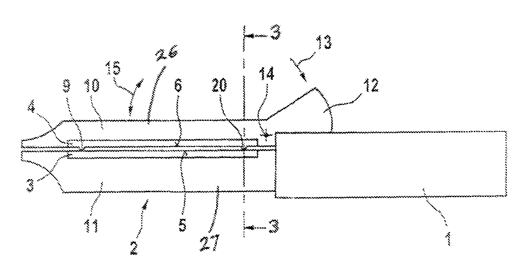
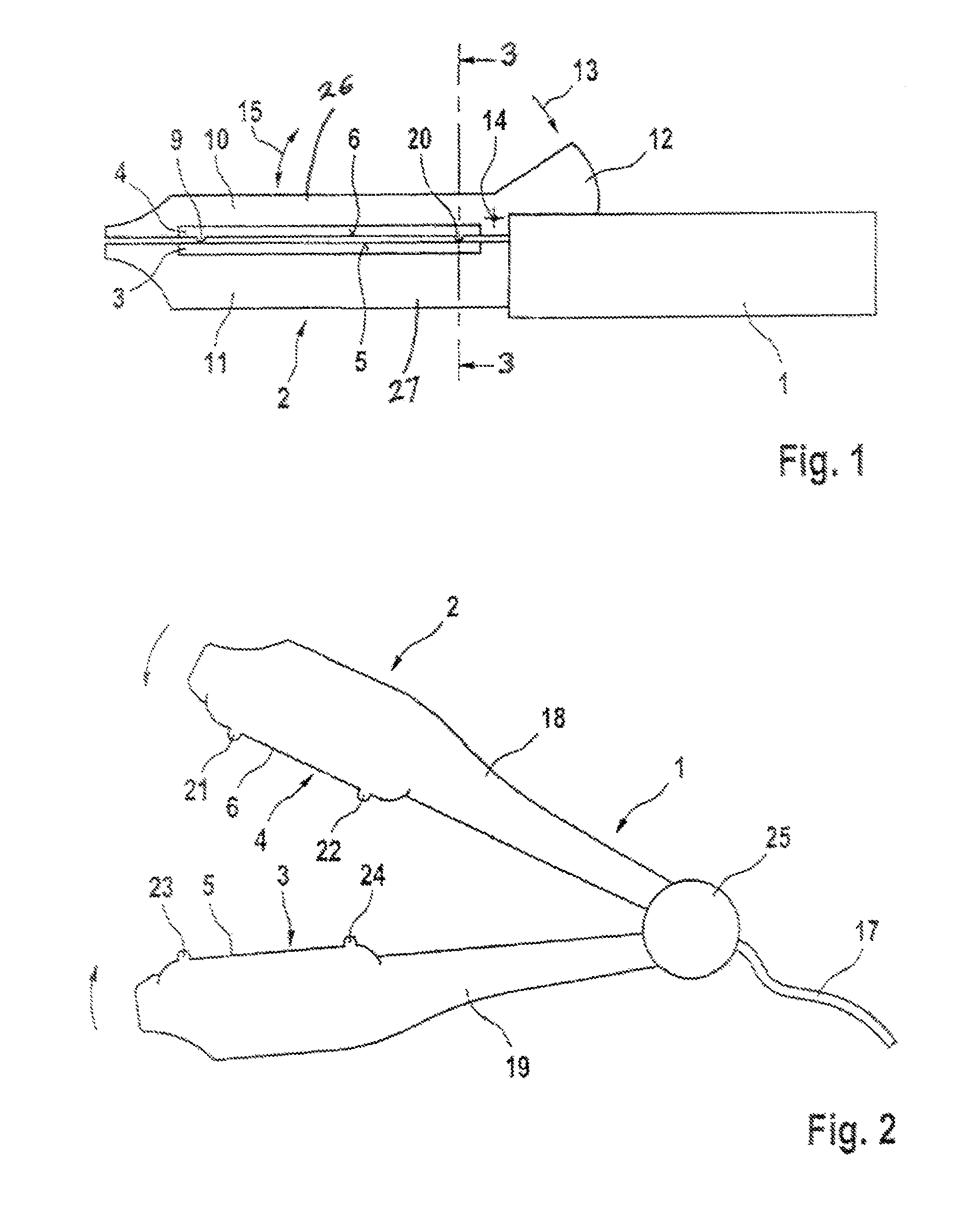
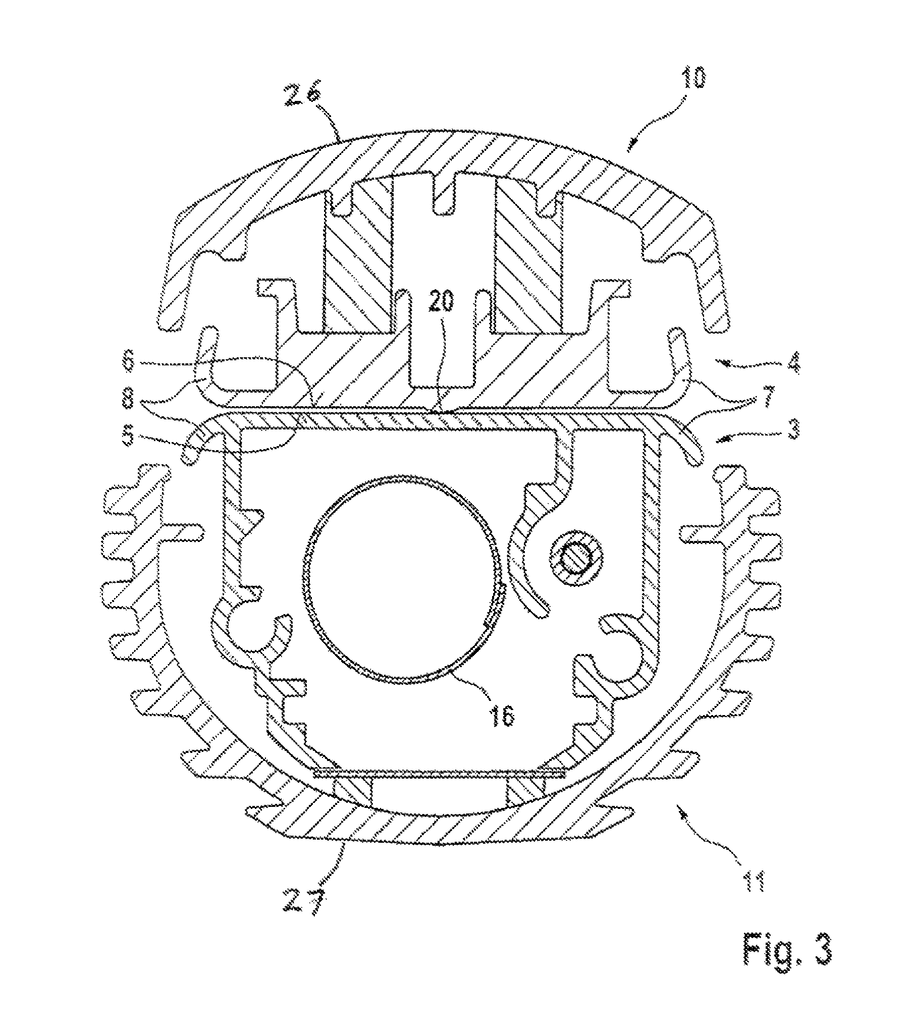
The hair styling device according to FIGS. 1 and 2 features a handle part 1 and a heater part 2. The heater part 2 is arranged on and forms an extension of the handle part 1 and may be electrically operated (see FIG. 2) or gas-operated (see FIGS. 1 and 3). The hair styling device according to FIG. 1 features an energy source in the form of an (not-shown) exchangeable gas cartridge that is arranged in the handle 1 and supplies a catalyst 16 (see FIG. 3) in the heating part 2 with energy in order to realize flameless combustion. The hair styling device according to FIG. 2 is connected to the power supply by means of a cable 17 in order to supply an (not-shown) electric heating device in the heater part 2 with energy.

In the hair styling device according to FIG. 1, the heater part 2 includes long-like arms 10, 11 that are pressed against one another by means of a spring force. In this case, one of the arms 11 is stationarily connected to the handle 1. The second arm 10 can be pivoted aw...


PUM

PropertyMeasurementUnit
roughnessaaaaaaaaaa
roughnessaaaaaaaaaa
roughnessaaaaaaaaaa

Abstract

A hair styling device with a handle part, at least one heater part and two metallic molded parts that are preferably made of aluminum or an aluminum alloy and serve, in particular, for straightening, curling or waving hair. Hairs can be inserted between facing contact surfaces of the molded parts and the molded parts can be changed from an open state into a closed state. In order to ensure particularly good sliding properties for the hair, the invention proposes that the contact surfaces are at least regionally provided with an enamel coating.

Description

TECHNICAL FIELDThe invention pertains generally to heated hair styling devices. More particularly, the invention pertains to hair styling devices with a handle, a heater and molded clamping implements for straightening, curling or waving hair.BACKGROUNDA hair styling device of this type is discussed, for example, in EP 1 030 571 B1. The metallic molded parts of this hair styling device are covered with a thin layer of lacquer or anodized, if the molded parts are made of aluminum or an aluminum alloy, treated by means of an anodizing method (in order to produce an oxide layer). These lacquer layers or oxide layers are respectively applied onto the molded parts in order to realize a smoother surface than that of non-treated metallic molded parts such that the hairs to be styled are subjected to the least mechanical stress possible when the hair styling device is used. The hairs are subjected to this stress due to the fact that the hair strands to be styled are clamped between the mold...

Claims


Application Information

Patent Timeline
Patent Type & Authority Patents(United States)
IPC IPC(8): A45D2/40A45D1/04
CPCA45D1/04
Inventor HENNINGER, FRIEDRICHSENG, JURGENLIEBENTHAL, DIETER
Owner BRAUN GMBH
Why Eureka
Try Eureka