Load drive control device

a control device and drive technology, applied in the direction of oscillator generators, electronic switching, pulse techniques, etc., can solve the problems of electromagnetic inference noise, and achieve the effect of power loss and heat generation, and reducing electromagnetic inference nois

Active Publication Date: 2017-10-03
HITACHI ASTEMO LTD
View PDF12 Cites 7 Cited by
  • Summary
  • Abstract
  • Description
  • Claims
  • Application Information

AI Technical Summary

Benefits of technology

[0020]According to the present invention, it is possible to provide a load drive slope control device that can reduce EMI noise, and power loss and heat generation when a drive transistor is turned on and off.
[0021]In addition, it is possible to provide a load drive slope control device that can reduce EMI noise when temperature is not excessively high, and protect a drive transistor from excessive high temperature-induced damage.
[0022]Tasks, configuration, and effects which have not been described above are apparent from embodiments to be described hereinbelow.

Problems solved by technology

When a drive transistor, which is connected to a load so as to drive the load (for example, a solenoid), is turned on and off for pulse width modulation (PWM) control such that the load is driven, electromagnetic inference (EMI) noise occurs due to high-frequency components of an output voltage from the drive transistor.

Method used


Image

  • Load drive control device
  • Load drive control device
  • Load drive control device

Examples


first embodiment

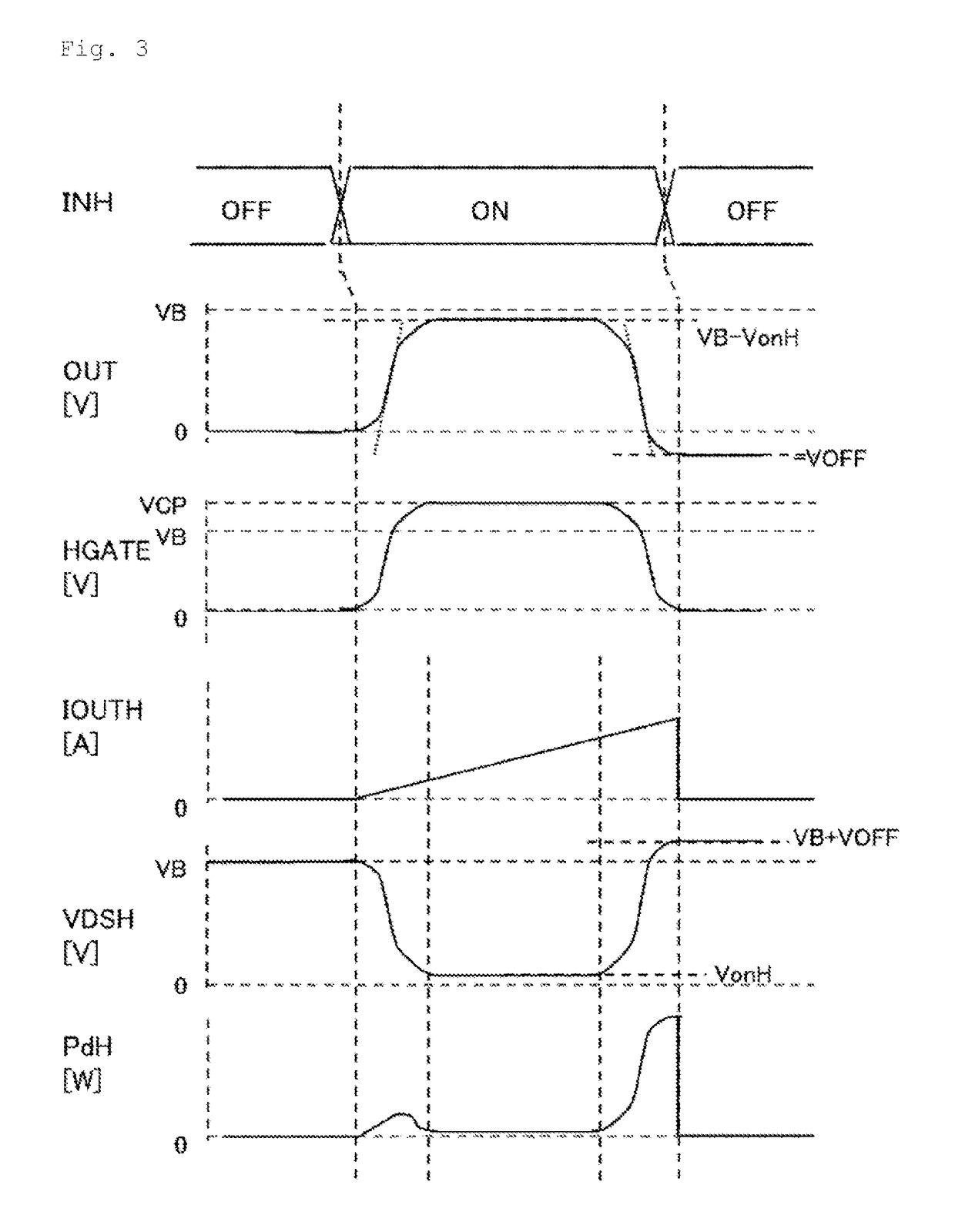
[0057]The configuration and the operation of a load drive slope control device 1 in a first embodiment of the present invention, which can reduce EMI noise, and reduce power loss and heat generation when a drive transistor is turned on and off, will be described.

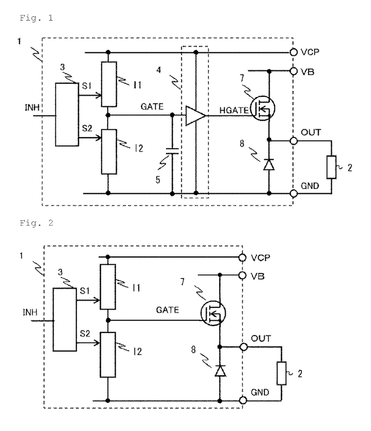
[0058]FIG. 1 illustrates the entire configuration of the load drive slope control device 1 in the first embodiment of the present invention which uses a high-side drive NMOS transistor.

[0059]The load drive slope control device 1 in FIG. 1 includes a power supply terminal VB; a load 2 which is a drive target; a high-side drive NMOS transistor 7 that is connected across the power supply terminal VB and the load 2; a pre-driver 4 that drives the gate of the high-side drive transistor 7; a capacitor 5 that is connected to an input GATE of the pre-driver 4; a first current source I1 that is ON / OFF controlled by a first signal S1, and generates current which is charged to the capacitor 5 connected to the input GATE of the pre-driv...

second embodiment

[0086]In a load drive slope control device in a second embodiment of the present invention which can reduce EMI noise, and reduce power loss and heat generation when a drive transistor is turned on and off, the configuration and the operation of the load drive slope control device with a low-side drive transistor configured to be connected to the GND terminal and to drive the load 2 will be described.

[0087]FIG. 9 illustrates a first example of the second embodiment of the present invention, and hereinafter, the points of difference between FIG. 9 and FIG. 1 illustrating a first example of the first embodiment will be described.

[0088]The load drive slope control device 1 in FIG. 9 includes the power supply terminal VB; the load 2 which is a drive target; a low-side drive PMOS transistor 10 that is connected across the GND terminal and the load 2; the pre-driver 4 that drives the gate of the low-side drive transistor 10; the capacitor 5 that is connected to the input GATE of the pre-d...

third embodiment

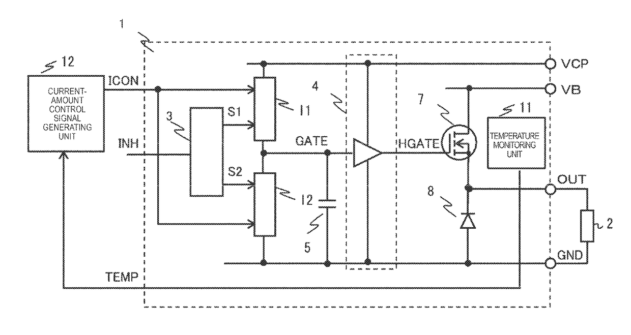
[0109]In a third embodiment of the present invention, the configuration and the operation of the load drive slope control device which reduces EMI noise when temperature is not excessively high, and prevents excessive high temperature-induced damage to a drive transistor at an excessive high temperature will be described.

[0110]FIG. 13 illustrates a first example of the third embodiment of the present invention, and hereinafter, the points of difference between FIG. 13 and FIG. 1 illustrating the first example of the first embodiment will be described.

[0111]In FIG. 13, the load drive slope control device includes a function of changing the amount of current of the first current source I1 and the second current source I2 via a current-amount control signal ICON, and includes a temperature monitoring unit 11, and a current-amount control signal generating unit 12 that correlates an output signal TEMP from the temperature monitoring unit 11 with the current-amount control signal ICON.

[0...


PUM


Abstract

Provided is a load drive slope control device that can reduce EMI noise, and power loss and heat generation when a drive transistor is turned on and off, and can prevent excessive high temperature-induced damage to the drive transistor at an excessive high temperature. Disclosed is a load drive control device including: a drive transistor that drives a load; a pre-driver that drives the drive transistor via an ON / OFF control terminal of the drive transistor; a capacitor that is connected to an input side of the pre-driver, a first current source that is ON / OFF controlled by a first signal, and generates current which is charged to the capacitor; and a second current source that is ON / OFF controlled by a second signal, and generates current for discharging the capacitor, in which an output voltage from the pre-driver is changed by charging or discharging the capacitor, the drive transistor is turned on and off by the output voltage from the pre-driver, and a linear ascending gradient and a linear descending gradient of the waveform of a voltage driving the load are obtained by turning on and off the drive transistor.

Description

TECHNICAL FIELD[0001]The present invention relates to a load drive control device, particularly, to a load drive slope control device that controls an ascending time and a descending time for the waveform of a voltage driving a load.BACKGROUND ART[0002]When a drive transistor, which is connected to a load so as to drive the load (for example, a solenoid), is turned on and off for pulse width modulation (PWM) control such that the load is driven, electromagnetic inference (EMI) noise occurs due to high-frequency components of an output voltage from the drive transistor.[0003]For this reason, EMI noise is reduced by sufficiently ensuring an ascending time and a descending time (hereinafter, also referred to as a gradient or a slope) for the waveform of a voltage driving a load via the charging or the discharging of the capacitance of an ON / OFF control terminal (for example, a gate terminal of a drive MOS transistor) of the drive transistor for driving the load with a current source (F...

Claims


Application Information

Patent Timeline
Patent Type & Authority Patents(United States)
IPC IPC(8): H03B1/00H03K3/013H03K17/08H03K17/16H03K3/012
CPCH03K17/16H03K3/012H03K3/013H03K17/08H03K17/164H03K2017/0806
Inventor KAWATA, TAKAHIROOURA, RYOICHISONEHARA, MASAHITOABE, YOSHITAKAYAMASHITA, TAKEO
Owner HITACHI ASTEMO LTD
Why Eureka
Try Eureka