

Electronic apparatus
a technology of electronic equipment and spread spectrum, applied in the direction of pulse generators, pulse techniques, instruments, etc., can solve the problem of high cost of clock application, and achieve the effect of reducing or suppressing the emi nois
- Summary
- Abstract
- Description
- Claims
- Application Information
AI Technical Summary
Benefits of technology
Problems solved by technology
Method used
Image

Examples
first exemplary embodiment
[0036]A. First Exemplary Embodiment
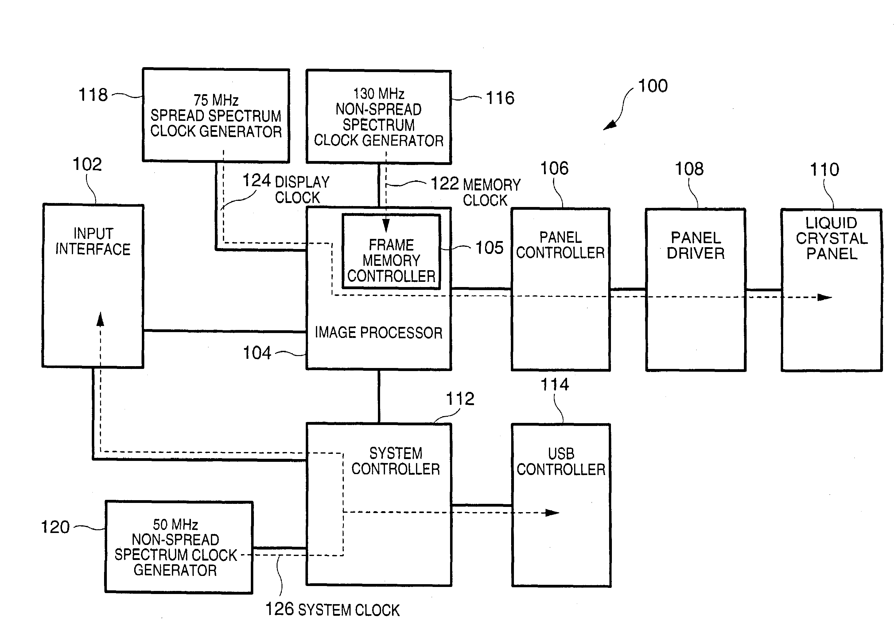
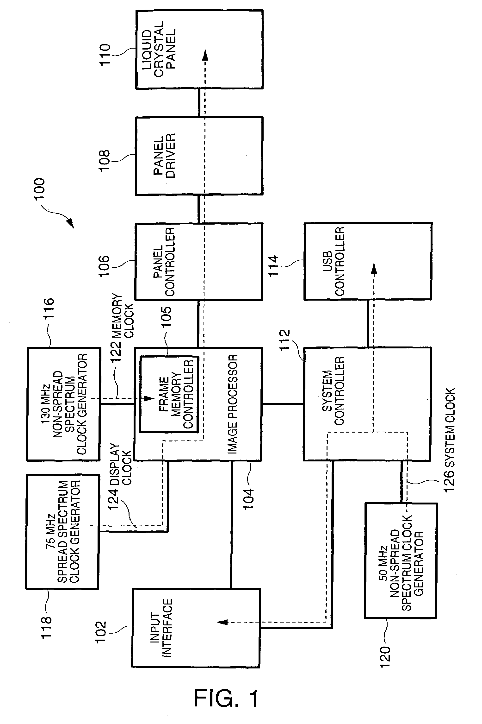
[0037]FIG. 1 is a schematic showing the construction of a liquid crystal projector to which the present invention is applied. A liquid crystal projector 100 shown in FIG. 1 is provided primarily with an input interface 102, an image processor 104, a panel controller 106, a panel driver 108, a liquid crystal panel 110, a system controller 112, a USB (Universal Serial Bus) controller 114, a 130 MHz non-spread spectrum clock generator 116, a 75 MHz spread spectrum clock generator 118, and a 50 MHz non-spread spectrum clock generator 120, any of which is constructed using an independent IC (Integrated Circuit). Among them, the image processor 104 has a frame memory controller 105 inside.
[0038]In the input interface 102, when the signal is an analog signal, A / D conversion is performed on an input image signal, which is fed to the image processor 104; when the signal is a digital signal, the signal is converted into the signal with a format that can be p...
second exemplary embodiment
[0051]B. Second Exemplary Embodiment
[0052]As described above, since the EMI noise is usually generated from the ICs using the clocks, the more the number of ICs becomes, the more the amount of EMI noise is generated by the clocks. In the above first exemplary embodiment, the spread spectrum is therefore applied to the clock used by the largest number of ICs from among plurality of types of clocks.
[0053]However, the EMI noise occurs from not only the ICs using the clocks but also from the wires establishing the connections among the ICs to carry the clocks.
[0054]Accordingly, in the present exemplary embodiment, the spread spectrum is applied to a clock that has the longest signal path from a clock generator generating the clock to an IC where the clock is ultimately provided.
[0055]For example, in the liquid crystal projector 100 shown in FIG. 1, the display clock 124 is provided from the 75 MHz spread spectrum clock generator 118 to the liquid crystal panel 110 at the destination the...
third exemplary embodiment
[0057]C. Third Exemplary Embodiment
[0058]As described above, the spread spectrum is applied to the clock used by the largest number of ICs among a plurality of types of clocks in the first exemplary embodiment as well as the clock having the longest signal path from the clock generator to the IC where the clock is ultimately provided.
[0059]In the contrast to the above, in the present exemplary embodiment, the spread spectrum is applied to the clock having the highest frequency.
[0060]As described above, the frequency spectrum of the EMI noise generally has the peaks of the amplitudes at the frequency (f1) of the clock and each of the frequencies (f2, f3 . . . ) corresponding to the harmonics thereof. Accordingly, when there are, for example, the 50 MHz clock and the 100 MHz clock as the clocks, both are compared with respect to a harmonic of 200 MHz. Since 200 MHz is a quadruple of 50 MHz and 100 MHz is a double of 50 MHz, the 100 MHz is lower in terms of the order of the harmonic. G...
PUM
 Abstract
Description
Claims
Application Information