Device and grounding device for enhancing ems and wireless communication device

a wireless communication and device technology, applied in the field of wireless communication devices, can solve the problems of enhancing emi noise owing to radiation or conduction, troubled system, etc., and achieve the effect of reducing the emi noise of differential pair routing and improving immunity against emi

Active Publication Date: 2013-07-04
CLIMAX TECH
View PDF1 Cites 7 Cited by
  • Summary
  • Abstract
  • Description
  • Claims
  • Application Information

AI Technical Summary

Benefits of technology

[0007]In view of this, a bridge is arranged near to a differential pair routing to reduce EMI noise of the differential pair routing and hence improve immunity against EMI.
[0008]In one embodiment, the invention provides a device for enhancing electromagnetic susceptibility, comprising: a first bridge, arranged near to a first trace of a differential pair routing and electrically connecting a radio frequency (RF) grounding with a analog grounding, wherein the RF grounding and the analog grounding are separated, the differential pair routing transmits signals between an RF circuit and an analog circuit, the first trace of the differential pair routing is closer to an antenna coupled to the RF grounding than a second trace of the differential pair routing, the RF circuit is coupled to the RF grounding, and the analog circuit is coupled to the analog grounding.
[0009]In another embodiment, the invention provides a grounding device for enhancing electromagnetic susceptibility, comprising: an RF grounding; an analog grounding, separated from the RF grounding; and a first bridge, arranged near to a first trace of a differential pair routing and electrically connecting the RF grounding with the analog grounding, wherein the differential pair routing transmits signals between an RF circuit and an analog circuit, the first trace of the differential pair routing is closer to an antenna coupled to the RF grounding than a second trace of the differential pair routing, the RF circuit is coupled to the RF grounding, and the analog circuit is coupled to the analog grounding.

Problems solved by technology

However, too much radiation power sometimes causes trouble to the system.
For example, enhancing the antenna efficiency may result in enhancing EMI noise owing to radiation or conduction.

Method used


Image

  • Device and grounding device for enhancing ems and wireless communication device
  • Device and grounding device for enhancing ems and wireless communication device
  • Device and grounding device for enhancing ems and wireless communication device

Examples


Embodiment Construction

[0021]The following description is of the best-contemplated mode of carrying out the invention. This description is made for the purpose of illustrating the general principles of the invention and should not be taken in a limiting sense. The scope of the invention is best determined by reference to the appended claims.

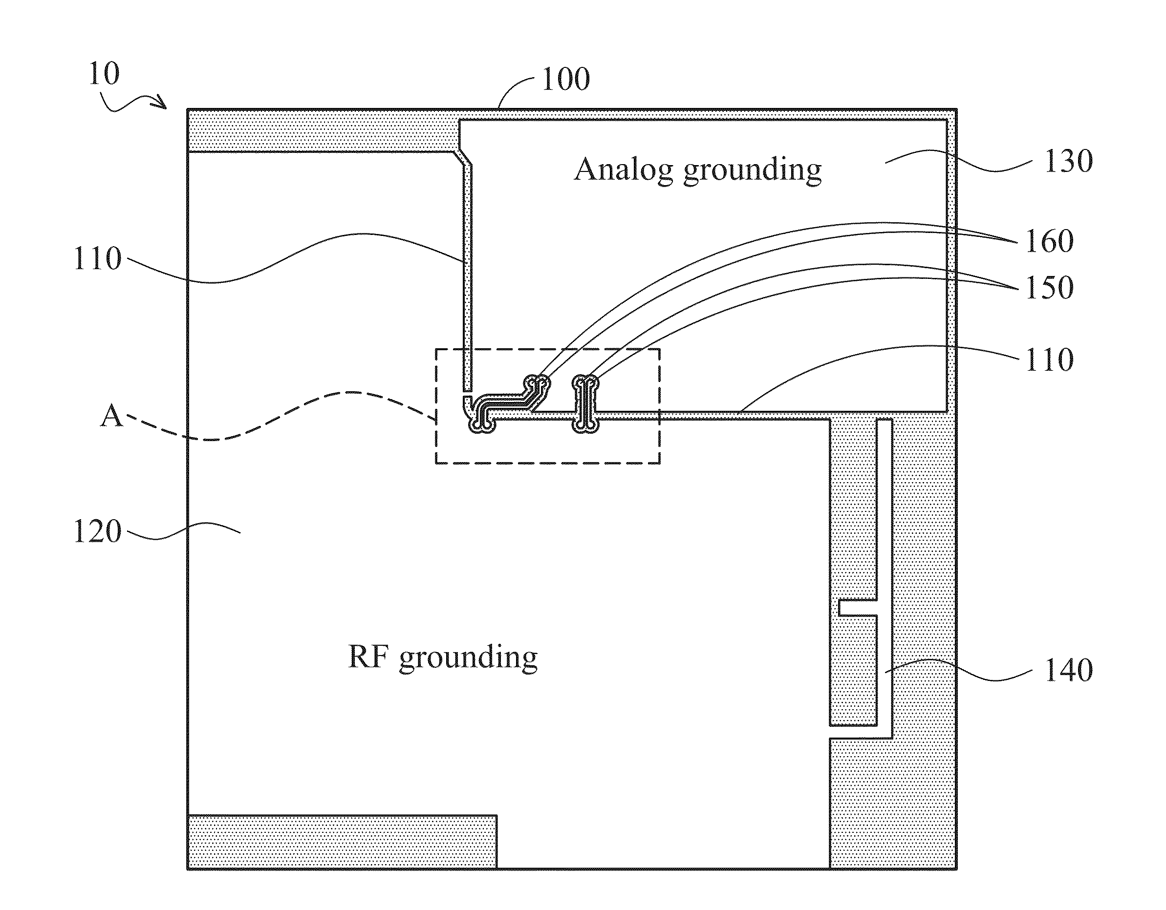
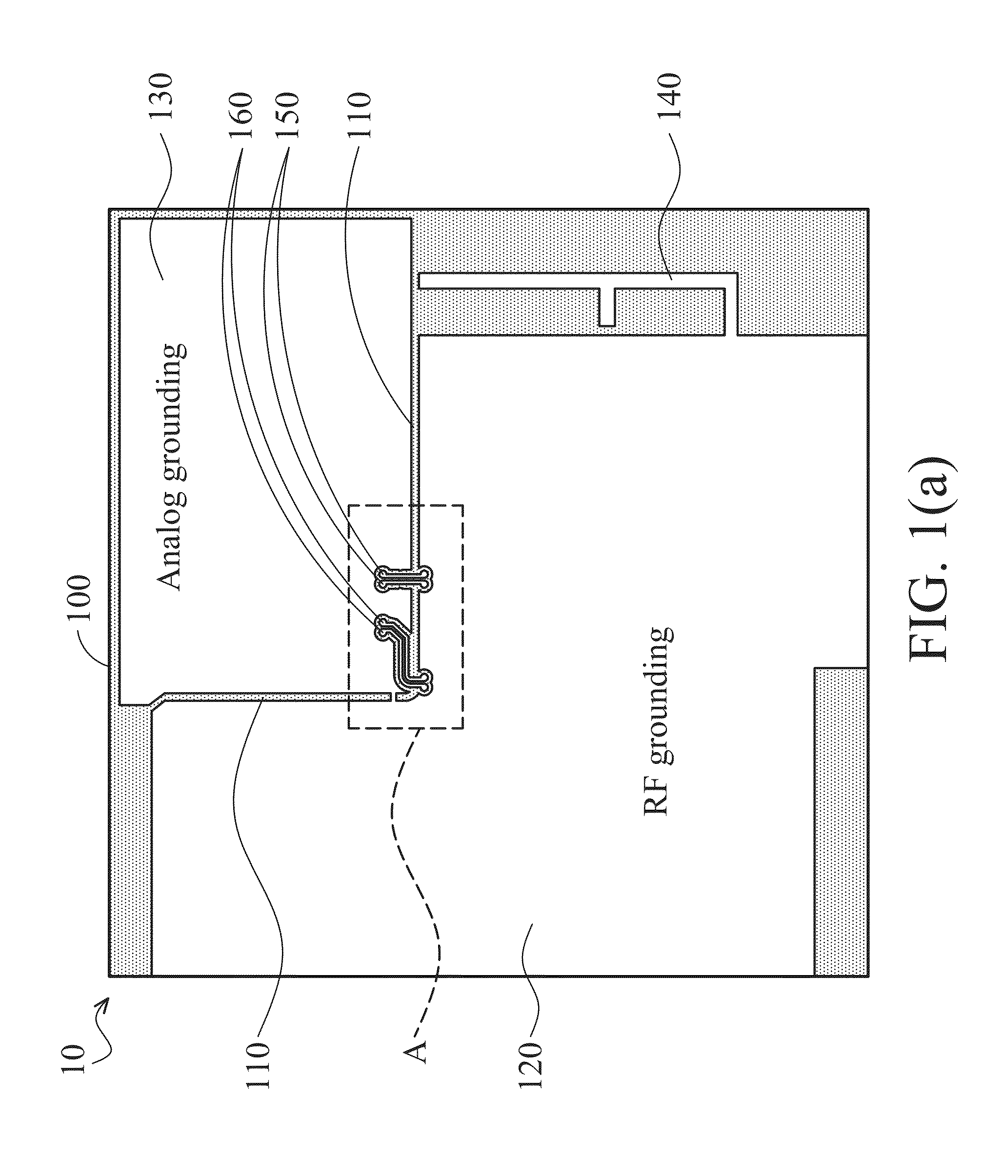
[0022]FIG. 3(a) shows a top view of a wireless communication device 30 according to an embodiment of the invention. FIG. 3(a) only shows a portion of the wireless communication device 30. The wireless communication device 30 comprises a printed circuit board 300 having an RF grounding 320 and an analog grounding 330. There is a moat 310 between the RF grounding 320 and the analog grounding 330, and hence the RF grounding 320 and the analog grounding 330 are separated groundings. In an example, the RF grounding 320 and the analog grounding 330 are metal layers. The RF grounding 320 is coupled to an RF module (not shown) for processing RF signals. The analog grounding 33...


PUM


Abstract

A device for enhancing electromagnetic susceptibility comprises a first bridge. The first bridge is near to a first trace of a differential pair routing and electrically connects an RF grounding with an analog grounding. The RF grounding and the analog grounding are separated. The differential pair routing transmits signals between an RF circuit and an analog circuit. The first trace of the differential pair routing is closer to an antenna coupled to the RF grounding than a second trace of the differential pair routing. The RF circuit is coupled to the RF grounding, and the analog circuit is coupled to the analog grounding.

Description

CROSS REFERENCE TO RELATED APPLICATIONS[0001]This Application claims priority of Taiwan Patent Application No. 101100137, filed on Jan. 3, 2012, the entirety of which is incorporated by reference herein.BACKGROUND OF THE INVENTION[0002]1. Field of the Invention[0003]The invention relates to wireless communication device and more particularly to a wireless communication device having separated groundings.[0004]2. Description of the Related Art[0005]For system-level layout design, good grounding is important. Generally, in order to suppress noise, the simplest and most effective way is to separate groundings with different properties, for example, groundings for analog and digital portions of circuitry. On the other hand, for signal trace routing, in order to avoid being influenced by EMI (Electromagnetic Interference), a differential architecture is a commonly used structure to improve EMS (Electromagnetic Susceptibility) of a system. For antenna design engineers, enhancing the effic...

Claims


Application Information

Patent Timeline
Patent Type & Authority Applications(United States)
IPC IPC(8): H05K1/11H01Q1/38
CPCH01Q1/38H01Q1/48H01Q9/42H05K2201/10098H05K1/0243H05K1/0245H05K1/0227
Inventor LIANG, HSIAO-PINCHANG, DAU-CHYRHCHEN, CHENG-WEI
Owner CLIMAX TECH
Why Eureka
Try Eureka