Working machine

a technology of working machine and headlight, which is applied in the direction of fixed installation, lighting and heating apparatus, lighting support devices, etc., can solve the problems of restricted headlight fitting angle, restricted headlight illumination range, and obscuring the headlight from the fron

Active Publication Date: 2011-12-06
KOMATSU LTD
View PDF12 Cites 2 Cited by
  • Summary
  • Abstract
  • Description
  • Claims
  • Application Information

AI Technical Summary

Benefits of technology

[0005]An object of the present invention is therefore to provide work machine capable of ensuring a substantial range of illumination for the headlights and capable of preventing an exhaust pipe from hindering forward illumination by the headlights.
[0024]With this work machine, the first positioning unit and the second positioning unit are provided at the coupling member. It is therefore possible to prevent the first headlight and the second headlight from being fitted at an erroneous angle.

Problems solved by technology

However, when a headlight is provided at the front surface of the canopy roof at an upper part of the operator's cab, it is feared that an exhaust pipe positioned to the front of the operator's cab may hinder the headlight from illuminating to the front.
It is therefore feared that the headlight fitting angle may become restricted as a result of an exhaust pipe hindering illumination and the range of illumination of the headlights may therefore become limited.
It is therefore difficult for the exhaust pipe to obstruct forward illumination by the first and second headlights even when the first and second headlights are arranged with an angle giving broad forward illumination.

Method used


Image

  • Working machine
  • Working machine
  • Working machine

Examples


Embodiment Construction

Structure

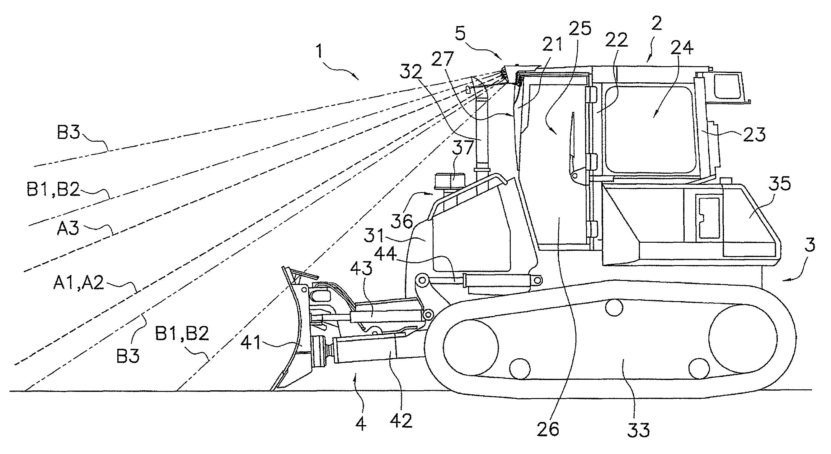
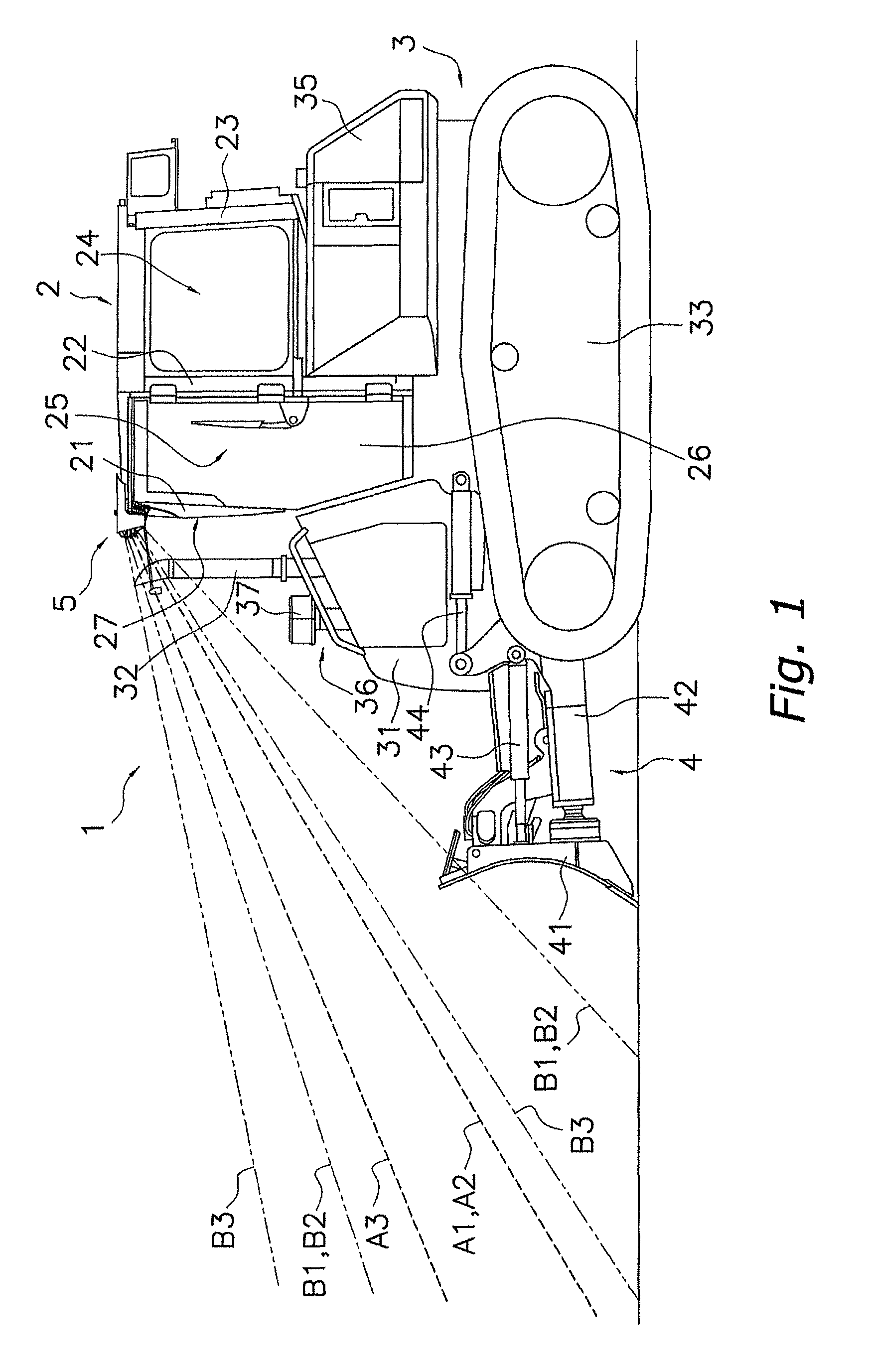
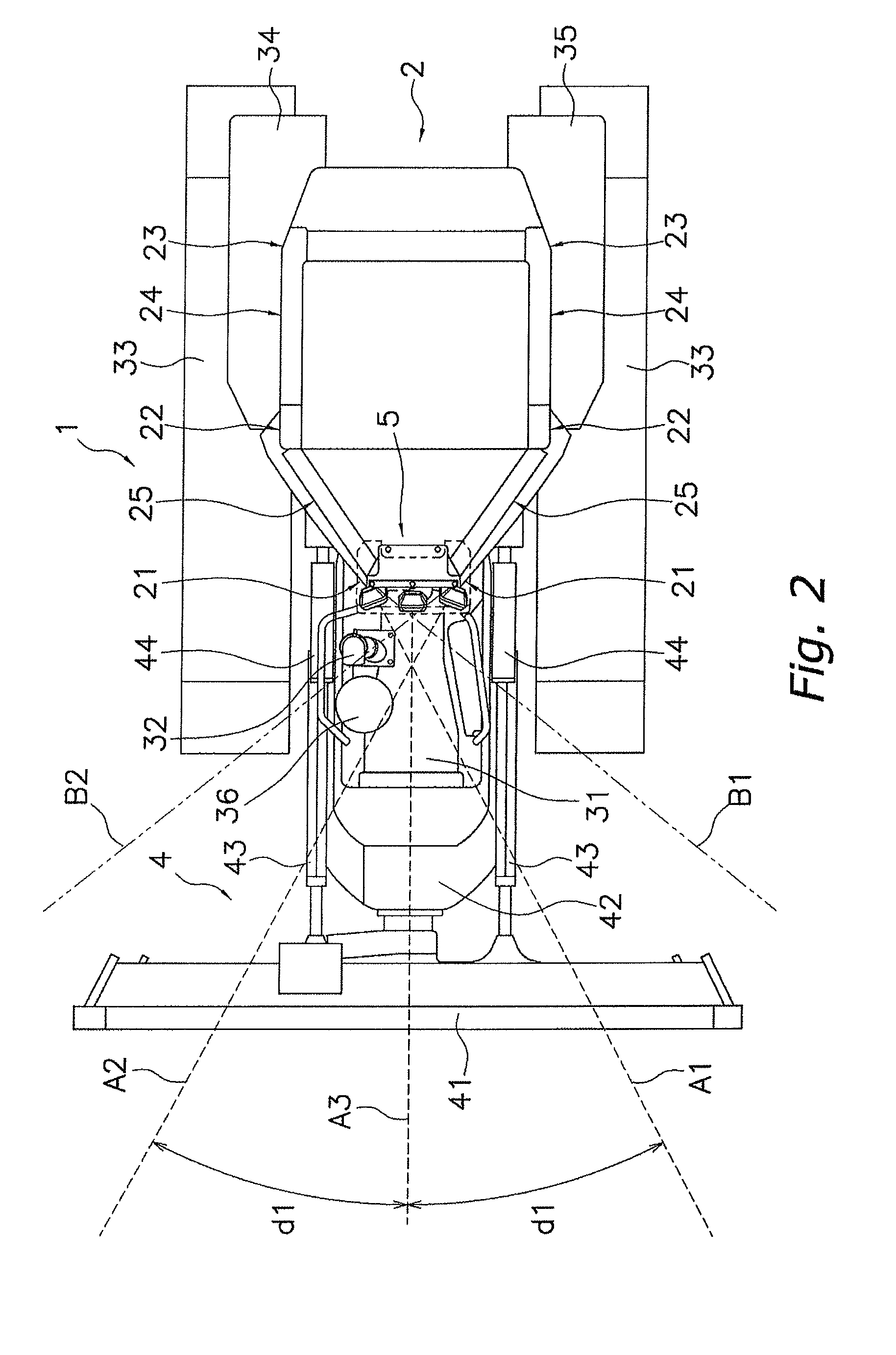
[0033]A work machine 1 of a first embodiment of the present invention is shown in FIG. 1 and FIG. 2. FIG. 1 is a side view of the work machine 1, and FIG. 2 is a plan view of the work machine 1. The work machine 1 is a crawler dozer that travels due to being driven by a crawler track and carries out various operations using work implement 4 provided at a front section. The work machine 1 has an operator's cab 2, a vehicle body 3, the work implement 4, and a lighting assembly 5.

Operator's Cab 2

[0034]A seat for an operator of the work machine 1 to sit on, a lever for performing various operations, a pedal, and various instruments for various operations are installed in the operator's cab 2. The operator's cab 2 has a roll-over protection structure (ROPS) and arranged above the vehicle body 3.

[0035]The operator's cab 2 has, in order from the front side, a pair of A-pillars 21, a pair of B-pillars 22, and a pair of C-pillars 23. Each of the pillars 21 to 23 are spaced in a late...


PUM


Abstract

The work machine has an operator's cab, an engine hood, an exhaust pipe, a first headlight, and a second headlight. The engine hood is disposed in front of the operator's cab. The exhaust pipe projects upwards from the engine hood. The first headlight and the second headlight are provided at a front part of the operator's cab spaced in a lateral direction and disposed so that optical axes of the first and second headlights are mutually intersect but not to overlap with the exhaust pipe when viewed in a top plan view.

Description

CROSS-REFERENCE TO RELATED APPLICATIONS[0001]This U.S. National stage application claims priority under 35 U.S.C. §119(a) to Japanese Patent Application No. 2006-053397, filed in Japan on Feb. 28, 2006. The entire disclosures of Japanese Patent Application No. 2006-053397 are hereby incorporated herein by reference.TECHNICAL FIELD[0002]The present invention relates to a work machine.BACKGROUND ART[0003]Work machines such as crawler dozers are provided with an engine hood to the front of an operator's cab. An exhaust pipe then projects upwards from the engine hood (refer to Japanese Laid-Open Patent Publication No. 2000-344008 (paragraph [0005], FIG. 1)). Work machines where headlights illuminating to the front are provided at the front left and right corners of the engine hood and where the headlights are provided at the front surface of a canopy roof at an upper part of the operator's cab also exist.SUMMARY OF THE INVENTION[0004]However, when a headlight is provided at the front su...

Claims


Application Information

Patent Timeline
Patent Type & Authority Patents(United States)
IPC IPC(8): B60Q1/32
CPCB60Q1/0483B60Q1/18E02F9/0866E02F9/0891E02F9/16E02F9/24B60Q2800/20
Inventor YOMOGITA, MAKOTOMIYAZAKI, MASAMICHIMUTO, KEITANAGAMI, KOJI
Owner KOMATSU LTD
Why Eureka
Try Eureka