LED vehicle lamp with frustum base plate

Pending Publication Date: 2022-10-06
SOUTH CHINA UNIV OF TECH
View PDF2 Cites 0 Cited by
  • Summary
  • Abstract
  • Description
  • Claims
  • Application Information

AI Technical Summary

Benefits of technology

The present patent aims to provide an LED vehicle lamp with a frustum base plate. The technical effects involve improving the distribution and illumination effect of the LED chips. This is achieved by allowing light emitted from the LED chips to be emitted towards the lateral space below the frustum base plate, without being blocked. This results in a larger illumination range and more uniform distribution of emitted light. The overall illumination effect of the LED vehicle lamp is improved.

Problems solved by technology

The following technical problems frequently exist: light emitted by the LED chips to the lower side of the cuboid base plate is easily blocked by an upper surface of the cuboid base plate and cannot be emitted to the lateral space below the cuboid base plate, so that the illumination range of the LED chips is reduced, the distribution of emitted light is not uniform enough, and the overall illumination effect of the LED vehicle lamp is affected.

Method used


Image

  • LED vehicle lamp with frustum base plate
  • LED vehicle lamp with frustum base plate
  • LED vehicle lamp with frustum base plate

Examples


embodiment i

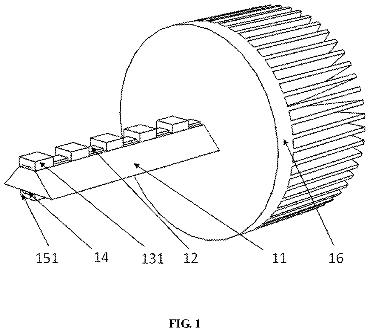
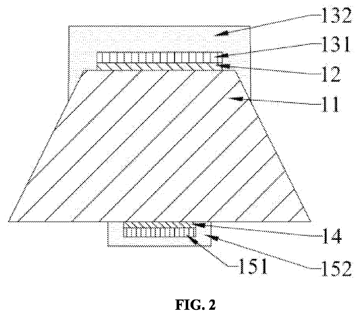
[0029]As shown in FIG. 1 to FIG. 2, an LED vehicle lamp with a frustum base plate includes a base plate, a circuit board and a plurality of LED chips. The base plate is a frustum base plate 11, which is arranged on the axis of the LED vehicle lamp. A width of an upper bottom surface of the frustum base plate 11 is smaller than that of a lower bottom surface of the frustum base plate. An axis of the circuit board is parallel to the axis of the frustum base plate 11. The width of the circuit board is smaller than that of the upper bottom surface of the frustum base plate 11. The circuit board is installed (such as welded) on the upper bottom surface of the frustum base plate 11 (namely a top surface of the frustum base plate 11). The plurality of LED chips are installed on the circuit board. In the embodiment, the width of the upper bottom surface of the frustum base plate 11 is 1 mm larger than that of the circuit board. The circuit board is a high-thermal-conductivity circuit board....

embodiment ii

[0044]The structures in the embodiment and the first embodiment are substantially the same, and have the following difference:

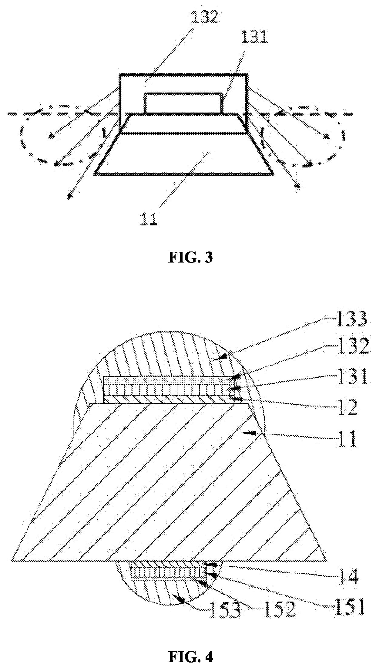
[0045]As shown in FIG. 4, the first phosphor includes a first fluorescent glue lens 133 and the first fluorescent glue 132. The first substrate is coated with the first fluorescent glue 132, and the lateral part of the first LED chip 131 and the first fluorescent glue 132 are coated with the first fluorescent glue lens 133. The second phosphor includes the second fluorescent glue 152 and a second fluorescent glue lens 153. The second substrate is coated with the second fluorescent glue 152. The lateral part of the second LED chip 151 and the second fluorescent glue 152 are coated with the second fluorescent glue lens 153. Both the first fluorescent glue lens 133 and the second fluorescent glue 153 lens are of spherical structures.

[0046]In the embodiment, the first fluorescent glue 132 is sprayed on the top surface of the first LED chip 131. The first fluoresc...

embodiment iii

[0048]The structures in the embodiment and the first embodiment are substantially the same, and have the following difference:

[0049]As shown in FIG. 5, the first phosphor includes the first fluorescent glue lens 133, and the lateral part of the first LED chip 131 and the first substrate are coated with the first fluorescent glue lens 133. The second phosphor includes the second fluorescent glue lens 153. The lateral part of the second LED chip 151 and the second substrate are coated with the second fluorescent glue lens 153. Both the first fluorescent glue lens 133 and the second fluorescent glue lens 153 are of spherical structures.

[0050]In the embodiment, the first fluorescent glue lens 133 is sprayed on the top surface of the first LED chip 131, and the width of the first fluorescent glue lens 133 is slightly larger than that of the upper part of the frustum base plate 11. Specifically, the top of the frustum base plate 11 is coated with the first fluorescent glue lens 133, and t...


PUM


Abstract

The present disclosure relates to an LED vehicle lamp with a frustum base plate. The LED vehicle lamp includes a base plate, a circuit board and a plurality of LED chips. The base plate is a frustum base plate. The frustum base plate is arranged on an axis of the LED vehicle lamp. A width of an upper bottom surface of the frustum base plate is smaller than that of a lower bottom surface of the frustum base plate. An axis of the circuit board is parallel to an axis of the frustum base plate. A width of the circuit board is smaller than that of the upper bottom surface of the frustum base plate. The circuit board is installed on the upper bottom surface of the frustum base plate, and the plurality of LED chips are installed on the circuit board.

Description

CROSS REFERENCE TO RELATED APPLICATIONS[0001]This patent application is a national stage application of International Patent Application No. PCT / CN2020 / 099927, filed on Jul. 2, 2020, which claims priority of Chinese Patent Application No. 201910592162.1 filed on Jul. 3, 2019, both of which are incorporated by reference herein in their entirety as part of the present application.TECHNICAL FIELD[0002]The present disclosure relates to the field of automotive illumination, and particularly relates to an LED vehicle lamp with a frustum base plate.BACKGROUND ART[0003]Along with the development of illumination technology, the LED lamp rapidly replace traditional lamps with the advantages of low power consumption, long service life, high brightness, low heat, environmental protection and the like to become a modern illumination tool with the widest global application range. At present, LED lamps are already popularized and applied to the vehicle industry, and various LED vehicle lamps in th...

Claims


Application Information

Patent Timeline
IPC IPC(8): F21S41/151F21S45/40
CPCF21S41/151F21S45/40H01L33/62H01L33/483H01L25/0753F21S41/192F21S41/148F21S41/176F21S45/47F21Y2107/90
Inventor LI, ZONGTAOYU, BINHAITANG, YONGYAN, CAIMANSONG, CUNJIANGZHAO, QILIANGRAO, LONGSHI
Owner SOUTH CHINA UNIV OF TECH
Why Eureka
Try Eureka