Bar-typed double-row LED lighting

a double-row led lighting and bar-type technology, applied in lighting applications, lighting source combinations, lighting and heating apparatuses, etc., can solve the problems of inefficiency of light dispersion, relatively high power consumption, and inconvenient installation of lighting equipmen

Active Publication Date: 2016-09-06
LIN WANJIONG +2
View PDF5 Cites 0 Cited by
  • Summary
  • Abstract
  • Description
  • Claims
  • Application Information

AI Technical Summary

Benefits of technology

[0006]Recently, a number of LED lighting apparatuses have been designed to replace the halogen apparatus, as well as other traditional incandescent or fluorescence lighting apparatuses. Especially, the LED lighting apparatuses are used in the super market, exhibition hall, museum, and so on because of long-life and energy-saving thereof. In some special situation, such as freezer, storage racks, exhibition cabin, etc. double-row LED lightings are adopted as the double-row LED lamp has bigger range of illumination than traditional single-row LED lighting. However, because of drawbacks of structure design or LED chip arrangement, the light emitted from one row LED lamp of double-row LED lighting is blocked by another row LED lamp, vice versa. As a result, the range of illumination of the LED lighting is reduced although it is bigger than that of single-row LED lighting. Moreover, shadow may be formed in the sides of the double-row LED lighting.

Problems solved by technology

However, such lighting apparatuses present a number of drawbacks.
For example, the popular halogen apparatus presents the following drawbacks, such as relatively high power consumption, inefficiency of light dispersion due to the placement of its metal shield in the line sight of the halogen bulb, and its limited effectiveness in preventing glare from the halogen bulb.
However, because of drawbacks of structure design or LED chip arrangement, the light emitted from one row LED lamp of double-row LED lighting is blocked by another row LED lamp, vice versa.

Method used


Image

  • Bar-typed double-row LED lighting
  • Bar-typed double-row LED lighting
  • Bar-typed double-row LED lighting

Examples


Embodiment Construction

[0012]The present invention is illustrated by way of example and not by way of limitation in the figures of the accompanying drawings. It should be noted that references to “an” or “one” embodiment in this disclosure are not necessarily to the same embodiment, and such references mean at least one.

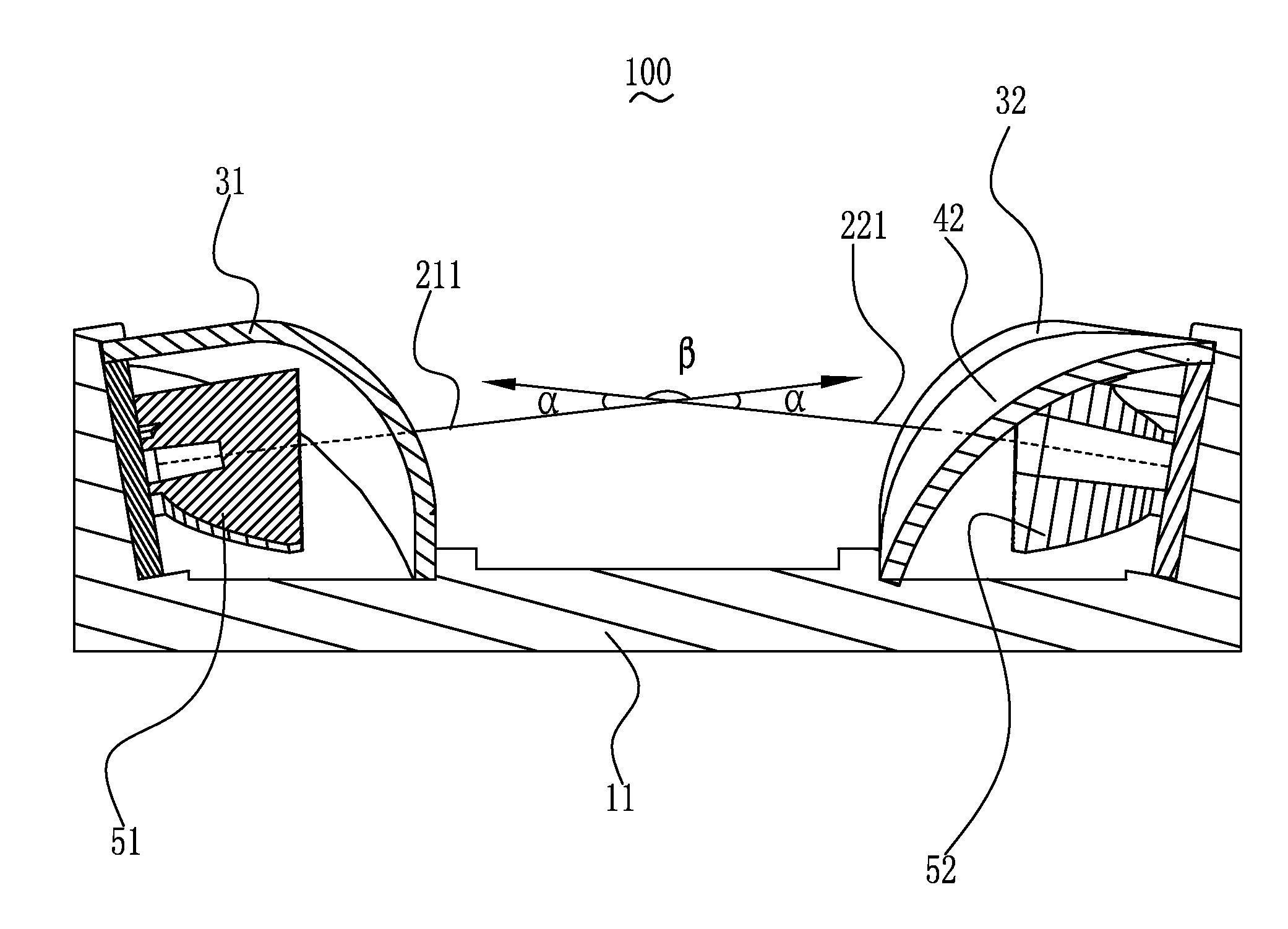
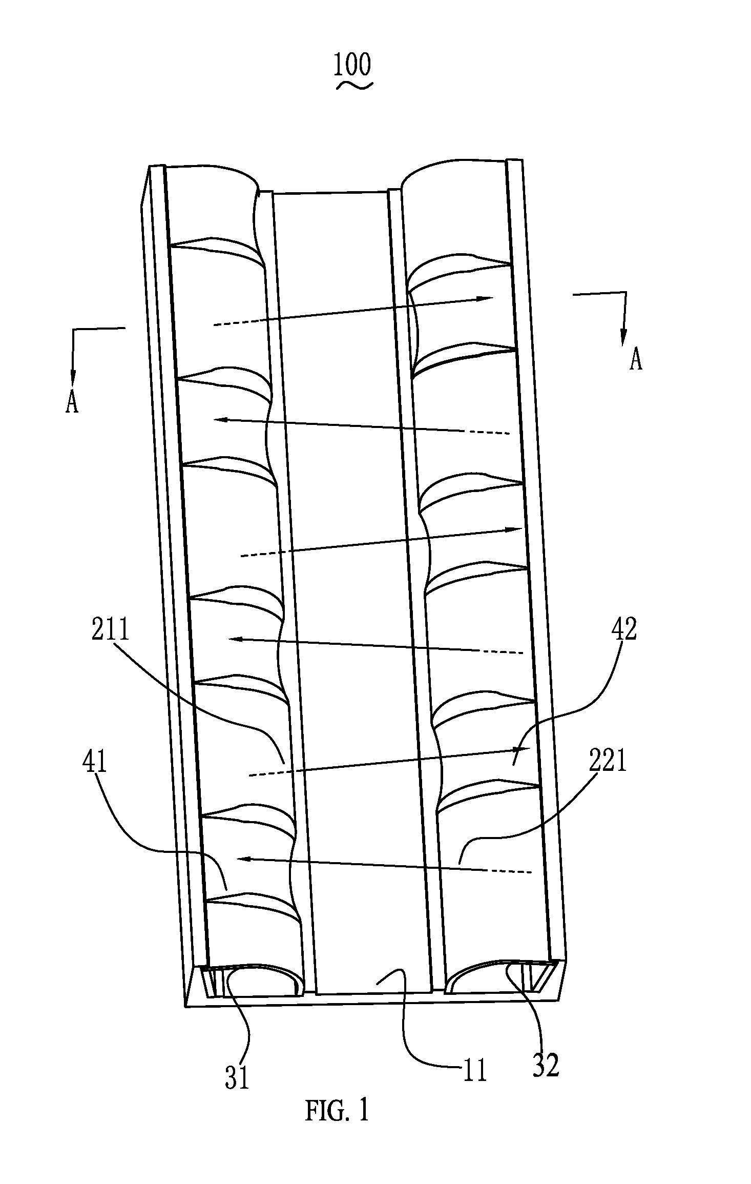
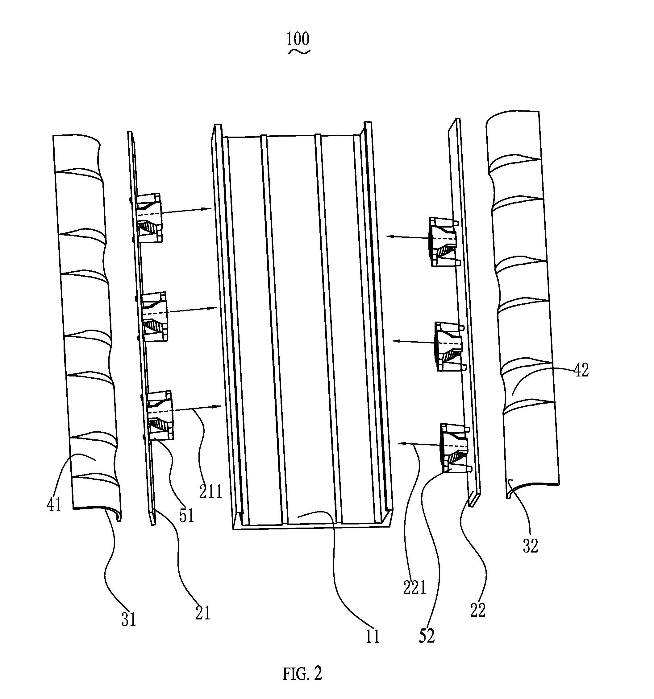
[0013]Referring to FIG. 1 to FIG. 2, a bar-typed double-row LED lighting 100 according to the present invention is shown. The bar-typed double-row LED lighting 100 includes an elongate shell 11, a first row LED lamp 21 disposed on the elongate shell 11, a second row LED lamp 22 disposed on the elongate shell 11 and spaced from and parallel to the first row LED lamp 21, a first cover 31 coupled onto the first row LED lamp 21, and a second cover 31 coupled onto the second row LED lamp 22. Understandably, the bar-typed double-row LED lighting 100 further includes other functional components, such as power, controlling devices, and so on, which is well known for a person skilled in the art.

[00...


PUM


Abstract

A bar-typed double-row LED lighting includes an elongate shell, a first row LED lamp, a second row LED lamp, a first cover, and a second cover. Each of the LED chips of the first row LED lamp is staggered from that of the second row LED lamp. The first cover includes a plurality of first depressions. The second cover includes a plurality of second depressions. Since each of the LED chips of the first row LED lamp is staggered from that of the second row LED lamp and the first, second covers respectively include a plurality of first, second depressions which are configured for avoiding or preventing the first, second covers from stopping the travel of the light emitted from the second first row LED lamps. As a result, the bar-typed double-row LED lighting can extend effective illumination area and improve luminous efficiency thereof.

Description

RELATED APPLICATION[0001]The present application claims the benefit of priority to the Chinese Application, CN201410228583.3, filed on May 28, 2014, the entire specification of which is incorporated herein by reference.BACKGROUND[0002]1. Technical Field[0003]The present application relates to lighting devices, and more particularly to a bar-typed double-row LED lighting.[0004]2. Description of the Related Art[0005]For years, people have used traditional incandescent or fluorescence lighting apparatus in order to address their interior lighting concerns. However, such lighting apparatuses present a number of drawbacks. For example, the popular halogen apparatus presents the following drawbacks, such as relatively high power consumption, inefficiency of light dispersion due to the placement of its metal shield in the line sight of the halogen bulb, and its limited effectiveness in preventing glare from the halogen bulb.[0006]Recently, a number of LED lighting apparatuses have been des...

Claims


Application Information

Patent Timeline
Patent Type & Authority Patents(United States)
IPC IPC(8): F21V1/00F21V3/02F21V13/02F21W131/40F21Y103/00F21Y113/00
CPCF21S4/28F21V3/02F21V13/02F21W2131/40F21Y2101/00F21Y2103/10F21Y2113/00F21Y2115/10
Inventor XU, GUOJUNPAN, HUANGFENG
Owner LIN WANJIONG
Why Eureka
Try Eureka