Apparatus for connecting panels

a technology of connecting panels and accessories, applied in the direction of couplings, rod connections, manufacturing tools, etc., can solve the problems of limiting the application and overall market acceptance of glass panels, the cost of glass panels, and the structure cos

Active Publication Date: 2011-12-13
SABIC GLOBAL TECH BV
View PDF48 Cites 56 Cited by
  • Summary
  • Abstract
  • Description
  • Claims
  • Application Information

AI Technical Summary

Problems solved by technology

However, the initial and subsequent costs associated with these systems limits their application and overall market acceptance.
The initial expenses associated with glass panel roofing systems comprise the cost of the glass panels themselves as well as the cost of the structure, or structural reinforcements, that are employed to support the high weight of the glass.
After these initial expenses, operating costs associated with the inherently poor insulating ability of the glass panels can result in higher heating expenses for the owner.
Yet further, glass panels are susceptible to damage caused by impact or shifts in the support structure (e.g., settling), which can result in high maintenance costs.
This is especially concerning for horticultural applications wherein profit margins for greenhouses can be substantially impacted due to these expenditures.
Connectors endure high forces over their service life.

Method used


Image

  • Apparatus for connecting panels
  • Apparatus for connecting panels
  • Apparatus for connecting panels

Examples


examples

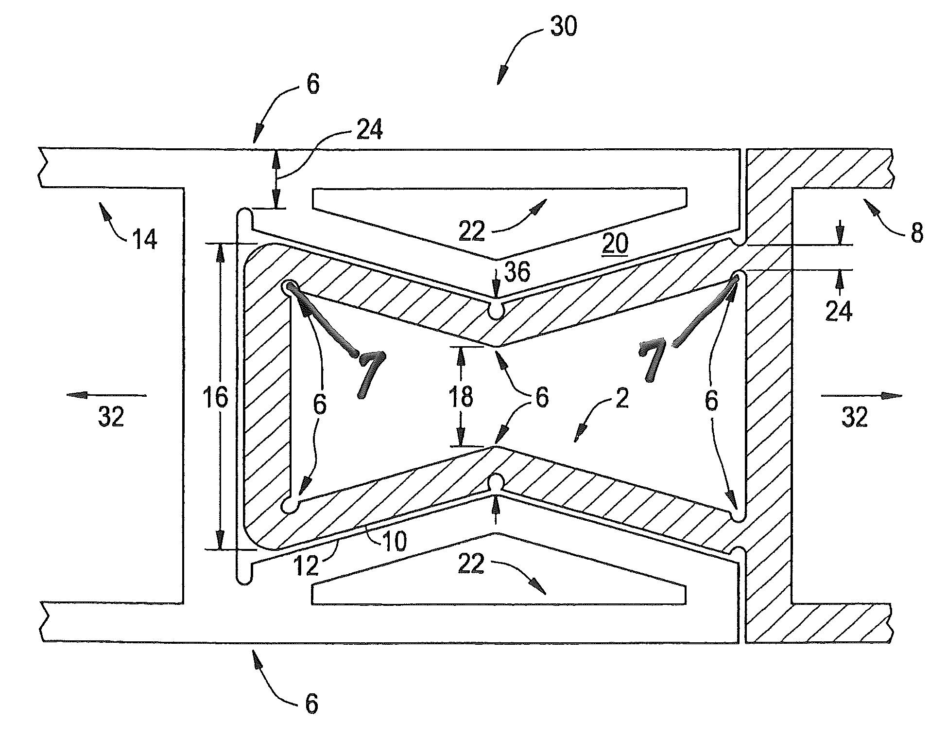
[0065]Referring now to FIG. 13, a graph illustrates the simulated contact pressure of a force expanding connector to a non-force expanding connector when acted upon by a disassembly force 32. To be more specific, referring to FIG. 14, a partial and cross-sectional view of the simulated force expanding connector, generally designated 90, is illustrated. Referring to FIG. 15, a partial and cross-sectional view of the simulated non-force expanding connector, generally designated 92, is illustrated. When these connectors (e.g., force expanding connector 90 and non-force expanding connector 92 were acted upon by a simulated disassembly force(s) 32, the simulated force expanding connector 90 produced a simulated peak contact pressure of about 4.5 megapascals, MPa (652.7 pounds per square inch, psi), whereas the simulated non-force expanding connector 92 produced a simulated peak contact pressure of about 3.25 MPa (471 psi). In addition, it can be seen that the in-plane displacement of the...


PUM

PropertyMeasurementUnit
lengthaaaaaaaaaa
lengthaaaaaaaaaa
lengthaaaaaaaaaa

Abstract

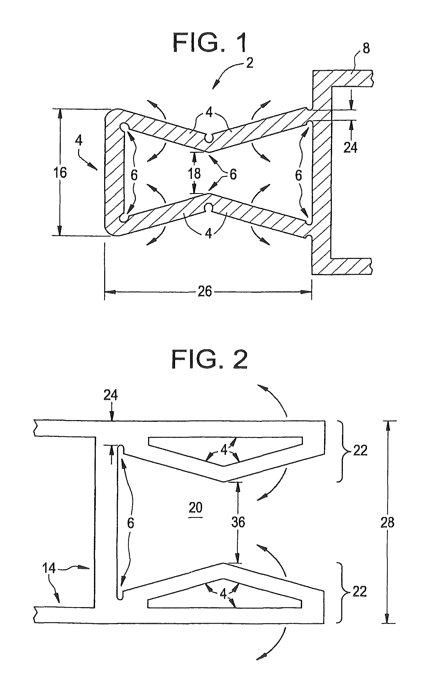
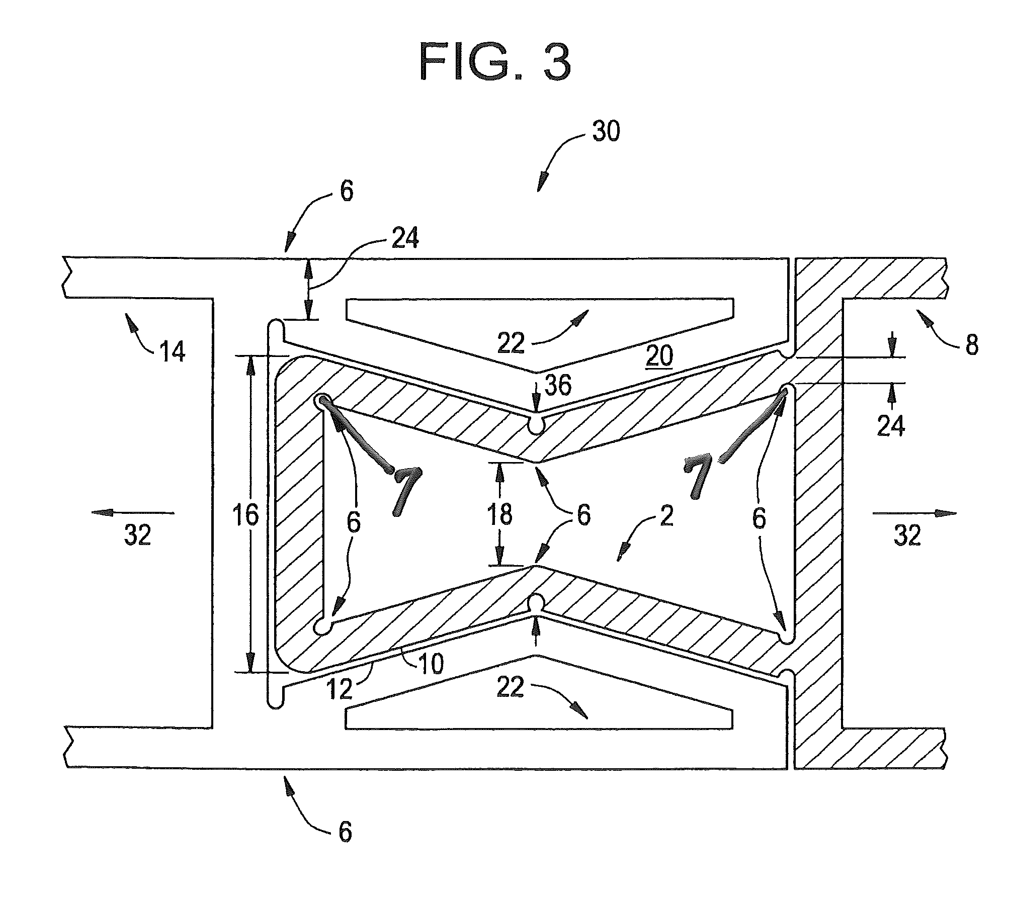
Disclosed herein are connectors for panels. In one embodiment a panel connector comprises, a connector comprising a rib-hinging geometry, wherein the rib-hinging geometry comprises living hinges, and wherein the rib-hinging geometry is capable of expanding in area. In another embodiment, a panel assembly is disclosed. The panel assembly comprises, a connector comprising a rib-hinging geometry, wherein the rib-hinging geometry comprises living hinges, a socket comprising an internal geometry, wherein the connector can be assembled to the internal geometry, and wherein the rib-hinging geometry is capable of expanding in area.

Description

TECHNICAL FIELD[0001]The present disclosure relates generally to connectors and joints for multiwall panels. More specifically, this application relates to connectors and joints for multiwall roofing or wall panels.BACKGROUND[0002]In the construction of naturally lit structures, such as greenhouses, pool enclosures, solar roof collectors, stadiums and sunrooms, glass panel roofs have been employed to allow natural light to shine therein. The glass panels themselves can be mounted in frame-like enclosures that are capable of providing a watertight seal around the glass panel and provide a means for securing the panel to a structure. These frame-like enclosures also provide for modular glass roofing systems that can be assembled together to form the roof.[0003]Glass panel roofing systems generally provide good light transmission and versatility. However, the initial and subsequent costs associated with these systems limits their application and overall market acceptance. The initial e...

Claims


Application Information

Patent Timeline
Patent Type & Authority Patents(United States)
IPC IPC(8): E04C3/00B25D17/04A63H33/06E04B2/00E04B7/08F16B7/00F16B2/02B21D53/84A63H33/08E04B2/08
CPCE04C2/543E04D3/28E04D3/32E04D3/366E04B1/6137Y10T403/5713E04D2003/285Y10T403/587Y10T403/535Y10T403/55F16B2200/71
Inventor THIAGARAJAN, CHINNIAHADRIAANSEN, FRANSKUMAR, BHAWESH
Owner SABIC GLOBAL TECH BV
Why Eureka
Try Eureka