Hose end fitting

Active Publication Date: 2011-12-20
DUNLOP OIL & MARINE
View PDF151 Cites 6 Cited by
  • Summary
  • Abstract
  • Description
  • Claims
  • Application Information

AI Technical Summary

Benefits of technology

[0010]The invention is especially applicable to the hose described in WO01/96772. We have made some improvement to the end fitting of the hose described in this application. These improvements m

Problems solved by technology

Furthermore, the outer wire may act to restrain excessive hoop deformation of the hose under high pressure.
The inner member used in the invention can in some circumstances cause a discontinuity in the bending stiffness at near the end of the hose making it prone to localisation of curvature, i.e. overbending, thereby disturbing the hose carcass formed by the helical wires of the hose.

Method used


Image

  • Hose end fitting
  • Hose end fitting
  • Hose end fitting

Examples


Embodiment Construction

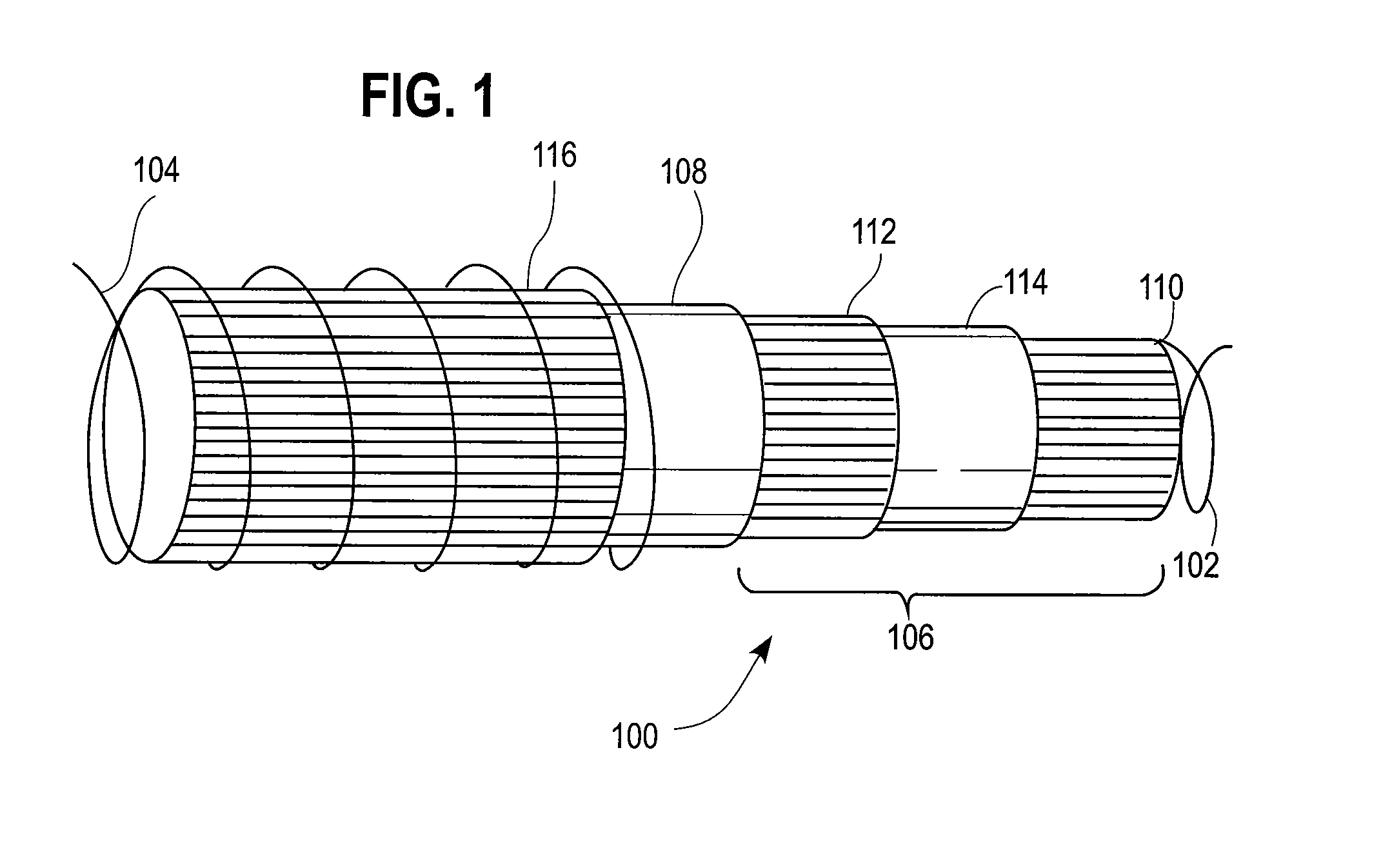
[0044]The type of hose to which this invention applies is described in detail in WO01 / 96772. FIG. 1 shows the hose 100 in more detail.

[0045]Briefly, the hose 100 comprises inner and outer gripping members 102, 104, which are preferably arranged in a helical form, and are preferably wires. Between the gripping members 102, 104 are arranged a tubular body 106 and an axial reinforcing braid 108, which surrounds the tubular body 106. The tubular body comprises an inner reinforcing layer 110, and outer reinforcing layer 112 and a sealing layer 114 arranged between the inner and outer reinforcing layers 110, 112. An outer protective / insulative layer 116 surrounds the braid 108. As mentioned above the hose 100 is described in greater detail in WO01 / 96772, the contents of which are incorporated herein by reference.

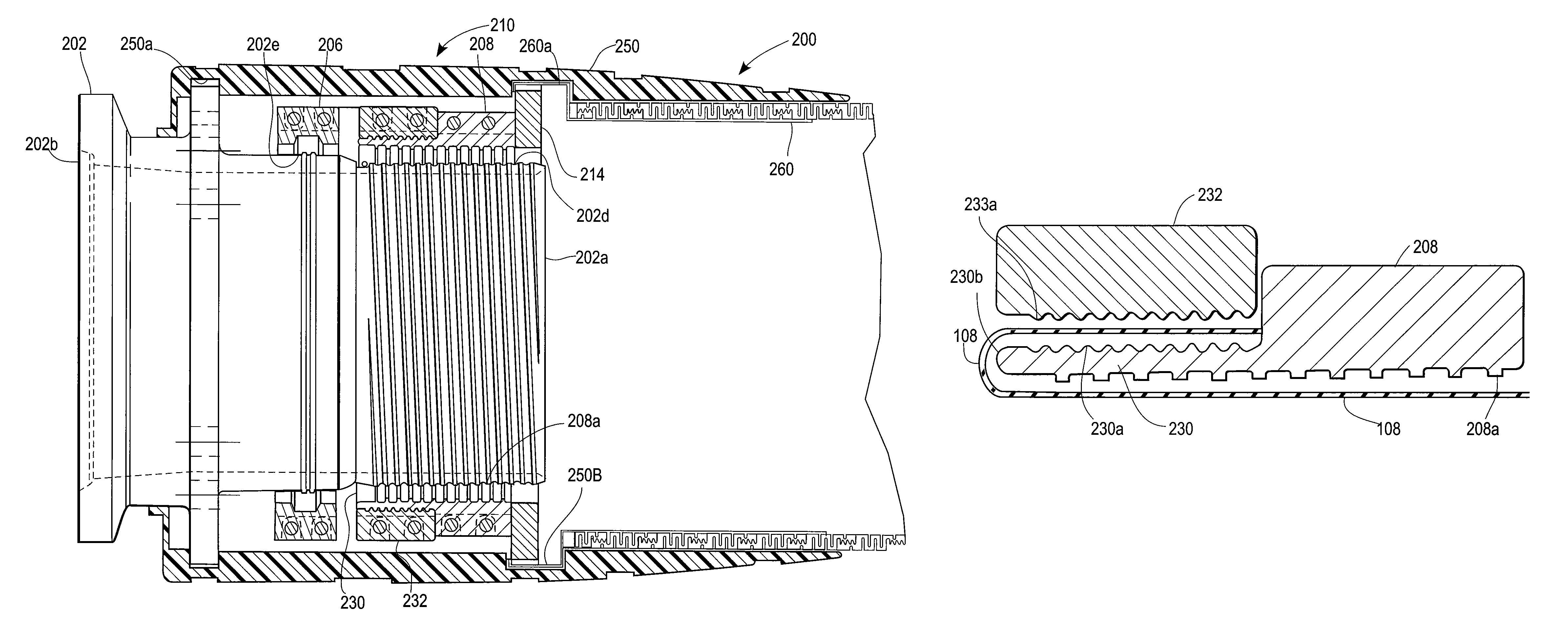
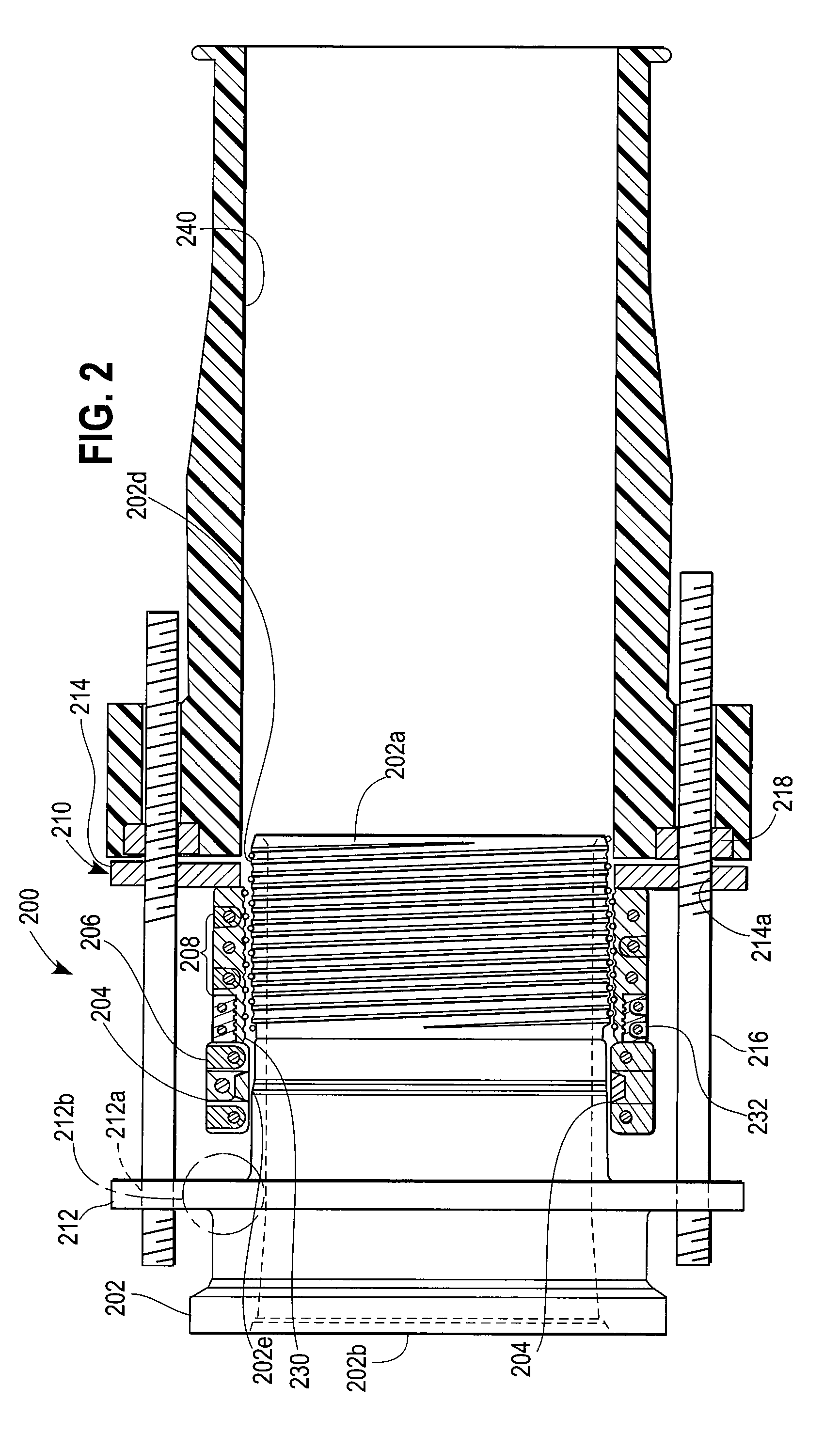
[0046]The ends of the hose may be sealed using the end fitting 200 shown in the figure. The hose has not been shown in the figure, in order to improve the clarity. The end fitting...


PUM

PropertyMeasurementUnit
Flexibilityaaaaaaaaaa

Abstract

An end fitting (200) for terminating an end of a hose comprising a tubular body of flexible material arranged between inner and outer helical wires, characterized in that the end fitting comprises: an inner member (202) adapted to be disposed at least partially within the hose; and a hose engaging member (208) adapted to press against the inner member 202 to retain the hose between itself and the inner member (202). The end fitting also includes a separate means for retaining one or more layers of the hose, the retaining means comprising an outer retaining member (232) adapted to press against an inner retaining member (230) to retain the or each layer of the hose between the outer and inner retaining members (232, 230) of the retaining means.

Description

[0001]This invention relates to hose, and more particularly relates to hose which can be used in cryogenic conditions. More specifically the invention relates to hose end fittings.BACKGROUND OF THE INVENTION[0002]Typical applications for hose involve the pumping of fluids from a fluid reservoir under pressure. Examples include supplying of domestic heating oil or LPG to a boiler; transporting produced oilfield liquids and / or gases from a fixed or floating production platform to the cargo hold of a ship, or from a ship cargo hold to a land-based storage unit; delivering of fuel to racing cars, especially during refuelling in formula 1; and conveying corrosive fluids, such as sulphuric acid.[0003]It is well known to use hose for the transport of fluids, such as liquefied gases, at low temperature. Such hose is commonly used to transport liquefied gases such as liquefied natural gas (LNG) and liquefied propane gas (LPG).[0004]In order for the hose to be sufficiently flexible, any given...

Claims


Application Information

Patent Timeline
IPC IPC(8): F16L33/00F16L33/01
CPCF16L33/01
Inventor WITZ, JOEL ARONCOX, DAVID CHARLESHALL, GERARD ANTHONYRIDOLFI, MATTHEW VERNONWORT, ANTHONY JAMESSMITH, RICHARD JAMES ANTHONY
Owner DUNLOP OIL & MARINE
Why Eureka
Try Eureka