Method for selective distribution of communications infrastructure

a technology of infrastructure and communications network, applied in the field of communications network operation, can solve the problems of large number of infrastructure equipment required, huge cost of deploying communications infrastructure units such as access points, wireless terminal points and base transceivers, and prohibitive costs of deploying such communications systems

Inactive Publication Date: 2012-01-17
PANASONIC CORP
View PDF10 Cites 9 Cited by
  • Summary
  • Abstract
  • Description
  • Claims
  • Application Information

AI Technical Summary

Problems solved by technology

There are a number of challenges with realizing such applications.
The primary among them is the cost of deploying communications infrastructure units such as access points, wireless terminal points and base transceiver stations.
Because of the geographic spread of wireless communications entities in these applications, a large number of infrastructure equipment are required.
The costs of deploying such communications systems would therefore be tremendous and prohibitive.
Furthermore, given their spread across large areas, few wireless communications entities will be provided service by each of the communications infrastructure units.
This results in limited use of the communications infrastructure.
Additionally, communications equipment units for large geographies require extensive cabling for interconnection.
This is further exacerbated by the limitations of cable lengths, such as the 100 meters limit on Ethernet cable lengths.
Naturally, these devices add costs to the realization of distributed wireless applications.
The limitations of wired cables prevent such deployments.
Related to the cost of the switches and routers, is the complexity of extending infrastructure control across such devices.
When communications infrastructure units of a distinct logical network cross network segments, their control is complicated.
Another complexity issue is the presence of network address translator (NAT) devices.
It is clear from these points, that the complexity of deploying distributed wireless applications over geographically diverse communications network is tremendous.
The diversity of traffic paths available in a mesh network makes route determination complex and time-consuming.
Furthermore, with the plurality of available routes across different mesh paths, there is significant overhead in the form of path status message exchange overheads and processing overheads—to determine the most appropriate route for traffic.
The overheads of route computation and management deter wide-spread deployments of mesh networks.
Consequently, geographically distributed wireless applications are not well supported by mesh networks.
Furthermore, the inherent uncertainty of wireless links complicates the efficiency of mesh network routing mechanisms.
Such problems of limited communications equipment coverage, interconnection complexity, mesh network route complications and costs severely restrict the deployment of communications networks capable of supporting geographically distributed wireless networks and applications.
However, such a method has no bounds of operation, which therefore makes it unpredictable and prone to errors or transmission loops.
The method however does not extend the geographic scope of the communications network infrastructure to mobile wireless terminals beyond the direct reach of the access point.
This method is limited to the operation of a single communications network entity and as such is not suitable for networks with large geographic scope.
It is not suitable for the reverse stream.
While each sector of an antenna helps in the creation of neighbourhood routes, the method does not overcome the problems of high operational complexity and costs.

Method used


Image

  • Method for selective distribution of communications infrastructure
  • Method for selective distribution of communications infrastructure
  • Method for selective distribution of communications infrastructure

Examples


embodiment 1

Distributing Infrastructure Functions

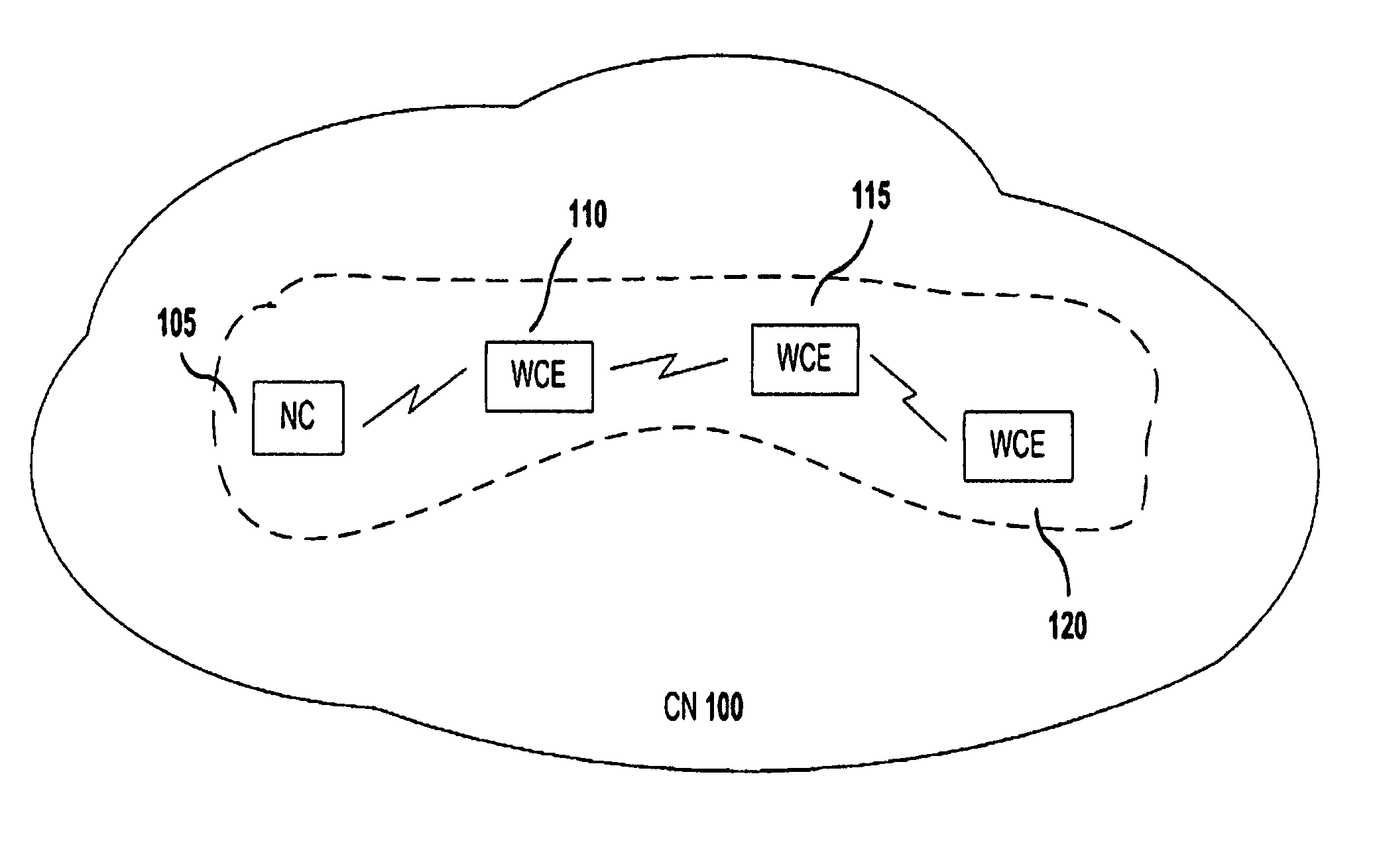
[0059]With reference to FIG. 1, a communications network (CN) (100) in accordance with the current invention is illustrated. CN (100) comprises a network controller (NC) (105) and a single or plurality of wireless communications entities (WCE) (110), (115) and (120).

[0060]NC (105) is representative of a controller entity capable of coordinating network resources, provisioning and configuring WCEs, such as WCE (110), (115) and (120), and coordinating communications flows among them. WCEs are representative of communications devices such as wireless access points and mobile terminals, capable of transmitting and receiving communications traffic.

[0061]In accordance with the invention for selective distribution of infrastructure functions, WCEs of CN (100) are organized in a multihop configuration, heretofore referred to as multihop chain. Each multihop chain of WCEs is connected to NC (105). Consequently, NC (105) communicates with WCEs over interme...

embodiment 2

Interconnection of WCEs

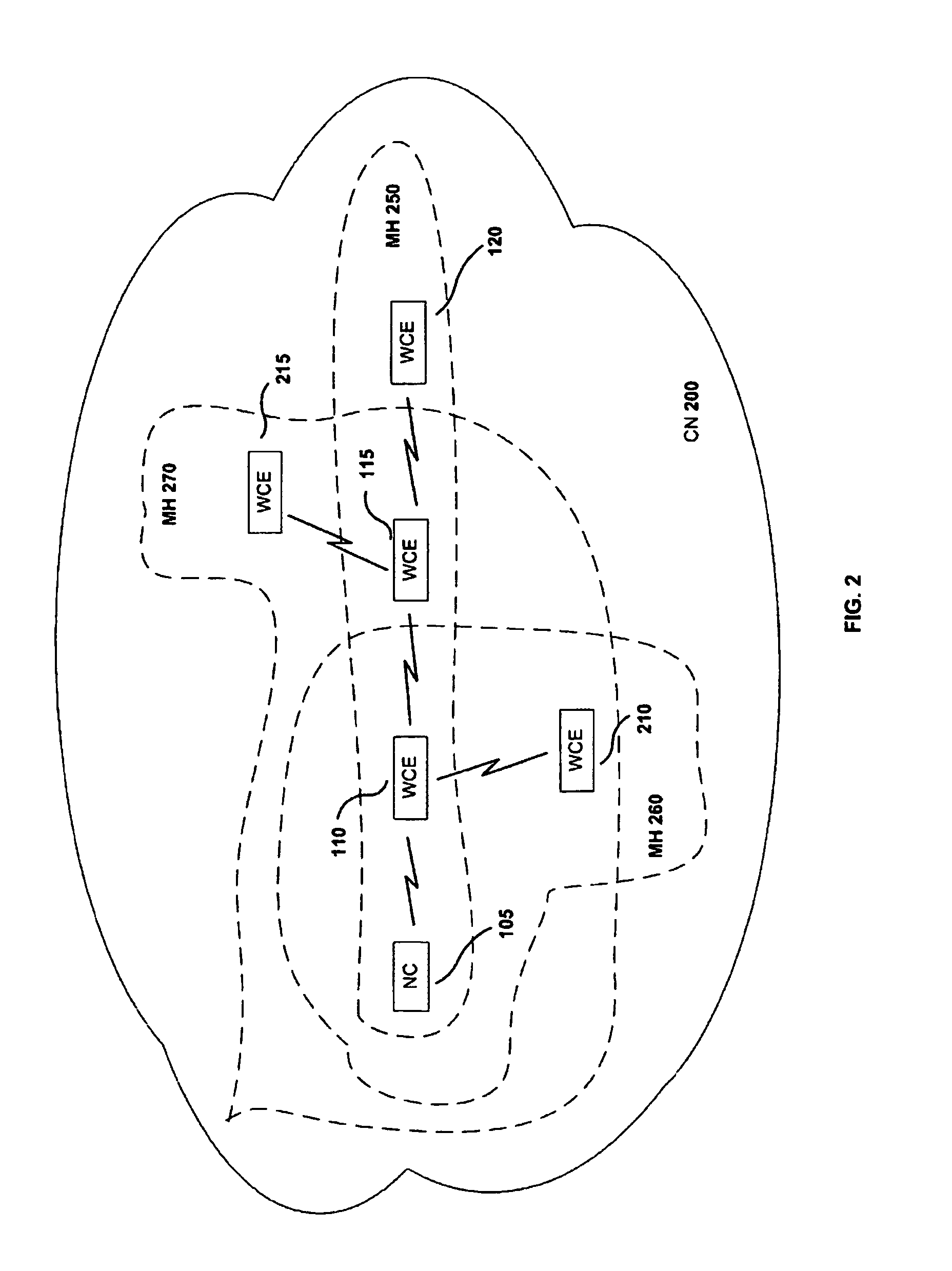
[0068]FIG. 2 is illustrative of a communications network CN (200) comprising a plurality of WCEs (110), (115), (120), (210) and (215). Each WCE is constituent of a single or plurality of logical multihop chains (MH) (250), (260) and (270). The WCEs are communicably coupled by wireless means. The coupling may be based on any single or plurality of wireless technologies such as Bluetooth, IEEE 802.11, IEEE 802.16, GPRS and WCDMA. The present invention of selective distribution of functions is applicable in all cases of wireless coupling means.

[0069]In accordance with the invention, each MH (250), (260) and (270) represent a distinct logical entity managed by NC (105). For instance, WCE (110) and (210) of MH (260) may be wireless cameras that are representative of the surveillance assets of a security organization with a centralized control entity in NC (105). As another example, WCE (110), (115) and (215) of MH (270) may be mobile terminals that are representati...

embodiment 3

Sequence of Switching Operations

[0074]The multihop chain configurations of the present invention comprise a network controller and WCEs coordinating their infrastructure functions (IF) and client functions (CF) operations in respective IF-mode and CF-mode. FIG. 3 is illustrative of a sequence of coordinated operations (300) among multihop chains MH (250), (260) and (270) of CN (200). WCE (110), (115) and (120) constitute MH (250). WCE (110) and (210) constitute MH (260). WCE (110), (115) and (215) constitute MH (270).

[0075]In the current embodiment, NC (105) has distributed infrastructure functions and associated parameters to each WCE of the multihop chains MH (250), (260) and (270). The WCEs are also made aware of coordination schedules for communications within a single or plurality of multihop chains.

[0076]In a time period (310), communications are conducted within MH (250). Here in a step (314), NC (105) operates in IF-mode and communicates with WCE (110), which operates in CF-...


PUM


Abstract

A wireless communication system is provided for configuring a multihop chain while suppressing the cost and complexity. In this system, one network controller (NC) (105) for executing the infrastructure function distributes the scheduling information to a plurality of communication entities (WCE) (110, 115, 120, 210, 215) configuring the multihop chain for alternating operation in the infrastructure function mode and the client function mode. The WCE (110, 115, 120, 210, 215) alternately operates the infrastructure function and the client function according to the distributed control and operations information.

Description

TECHNICAL FIELD[0001]The present invention pertains to operations of communications networks and, more particularly, it relates to the selective distribution of infrastructure functions among a plurality of communications entities.BACKGROUND ART[0002][Prior-Art 1] U.S. Pat. No. 6,097,703 A, “Multi-hop packet radio networks,” August 2000.[0003][Prior-Art 2] U.S. Pat. No. 6,659,947 B1, “Wireless LAN architecture for integrated time-critical and non-time-critical services within medical facilities,” December 2003.[0004][Prior-Art 3] US 2005 / 010 0045 A1, “Access points with selective communication rate and scheduling control and related methods for wireless local area networks (WLANs),” May 2005.[0005][Prior-Art 4] US 2005 / 007 8636 A1, “System and method of handling IP layer mobility in a wireless network,” April 2004.[0006][Prior-Art 5] US 2002 / 017 6390 A1, “Wireless mesh network node,” Nov. 2002.[0007]Wireless technologies are applied to diverse applications. Increasingly, they are us...

Claims


Application Information

Patent Timeline
Patent Type & Authority Patents(United States)
IPC IPC(8): H04W4/00H04W40/04H04W84/18H04W88/04
CPCH04W84/18H04W88/04
Inventor GOVINDAN, SARAVANANTAN, PEK YEW
Owner PANASONIC CORP
Why Eureka
Try Eureka