
Molds opening/closing group of a forming glass machine items

a technology of forming glass machine items and opening/closing groups, which is applied in glass blowing apparatus, glass making apparatus, glass shaping apparatus, etc., can solve the problems of impairing the quality of finished items, the uninstallable of the above-mentioned mold opening/closing group in the last-generation forming section,

Inactive Publication Date: 2012-02-14
BOTTERO SPA
View PDF10 Cites 7 Cited by
  • Summary
  • Abstract
  • Description
  • Claims
  • Application Information

AI Technical Summary

Benefits of technology

"The present invention provides a mold opening / closing group for a glass item forming machine that is straightforward and low-cost. The group includes two half-molds and handling arms that can be coupled to the half-molds and driven to rotate between open and closed positions. The driving means includes a linear actuator and a mechanical transmission interposed between the handling arms and the linear actuator. The linear actuator has a mobile member that translates parallel to the fixed hinge axes, and the mechanical transmission includes guide-and-slide assemblies for each handling arm. The guide-and-slide assembly has a guide that extends perpendicularly to the fixed hinge axes and the direction. This design simplifies the process of opening and closing the mold, reduces the cost, and improves the efficiency of the glass item forming machine."

Problems solved by technology

Though widely used in conventional forming sections, known mold opening / closing groups of the above type are practically uninstallable in last-generation forming sections, mainly on account of their bulk in the forming direction.
The bulk of the opening / closing group in the forming direction also poses various problems when removing the group from the section, e.g. for routine servicing or in the event of a malfunction, on account of removal also involving removal of other component parts of the section.
Moreover, in known transmissions, if one of the linkages connecting the actuator to the relative arm should for any reason be overloaded with respect to the other, consistent positioning of the half-molds, especially in the closed position, is no longer assured, thus impairing the quality of the finished items.

Method used


Image

  • Molds opening/closing group of a forming glass machine items
  • Molds opening/closing group of a forming glass machine items
  • Molds opening/closing group of a forming glass machine items

Examples


Embodiment Construction

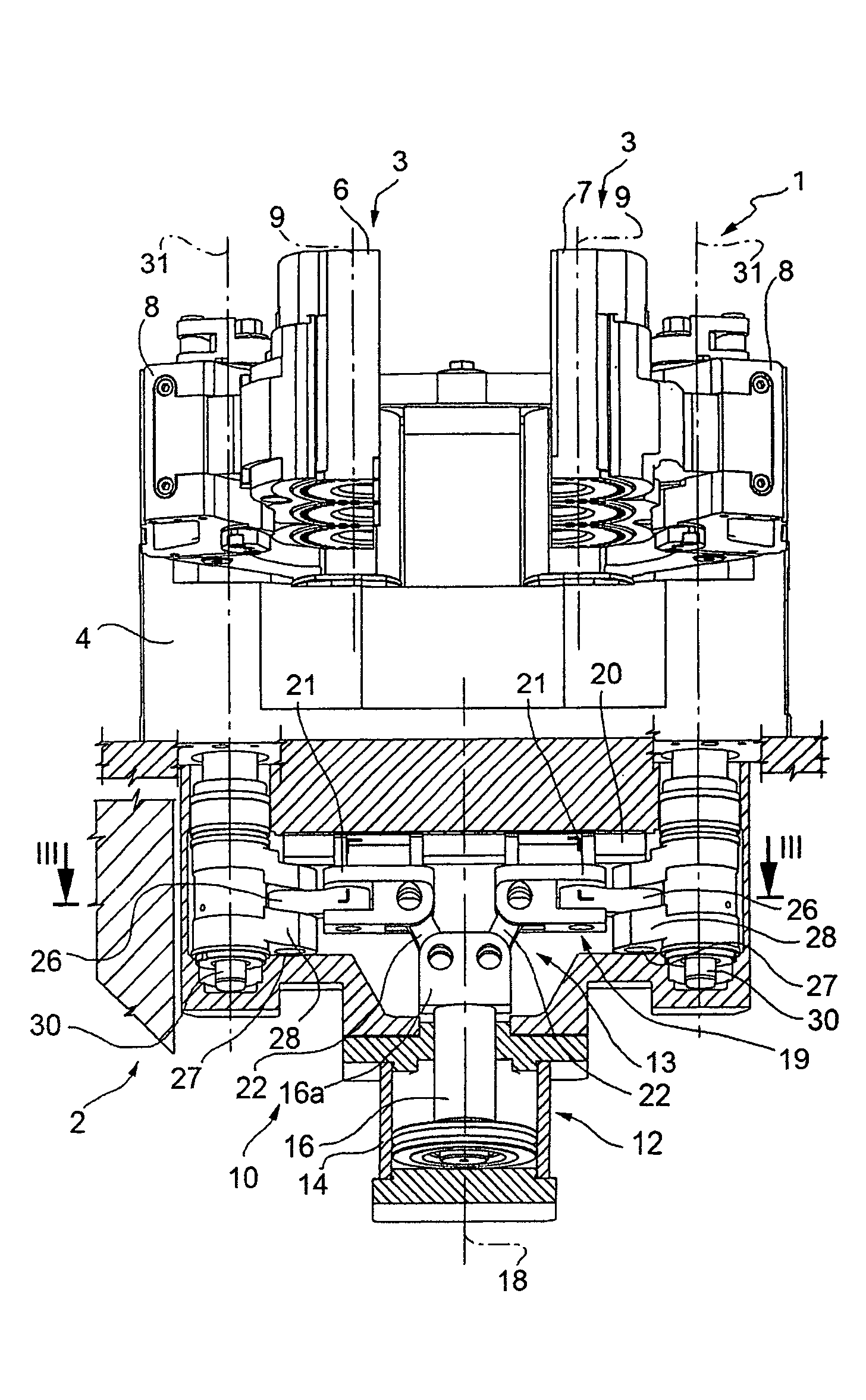
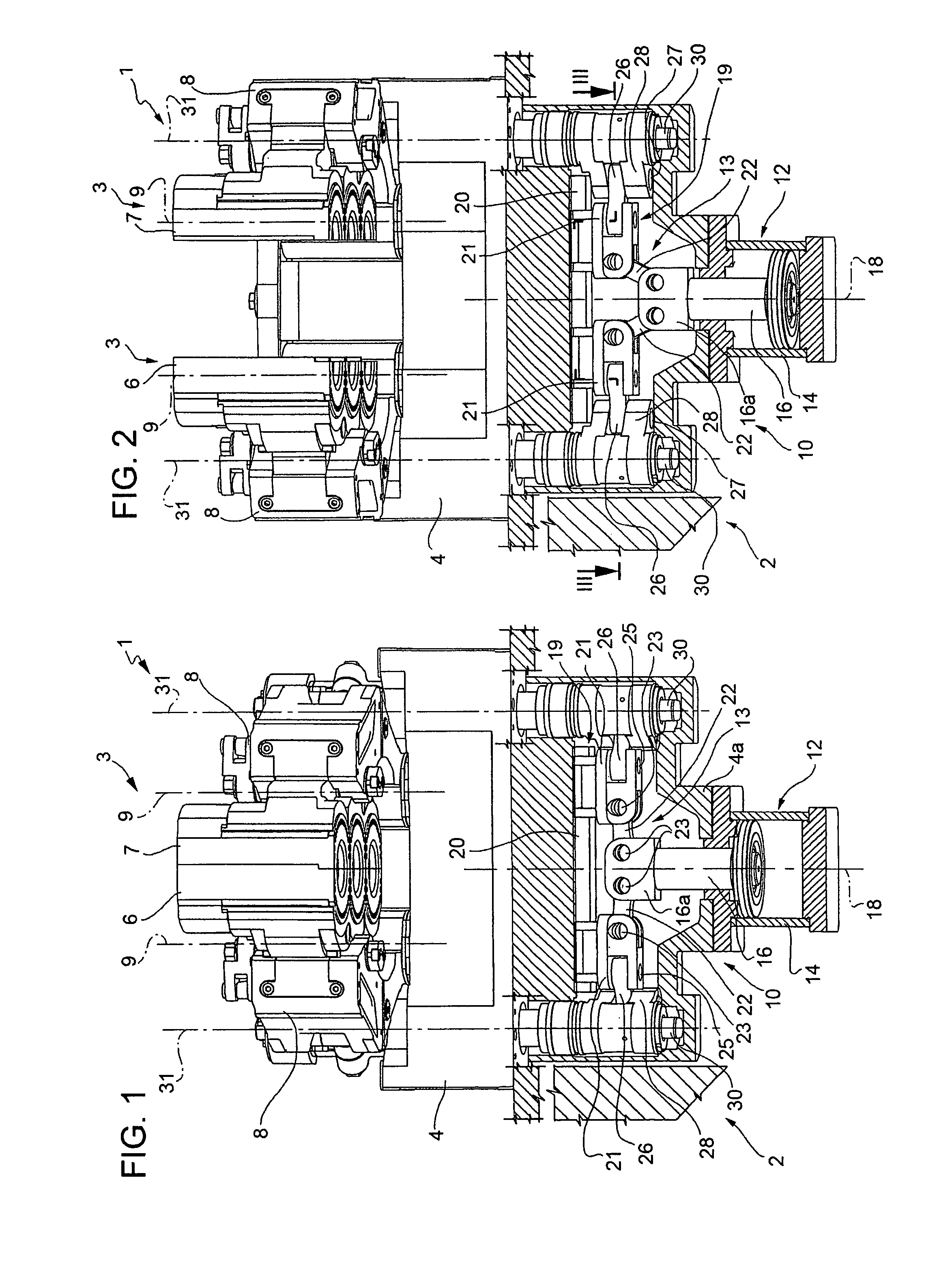
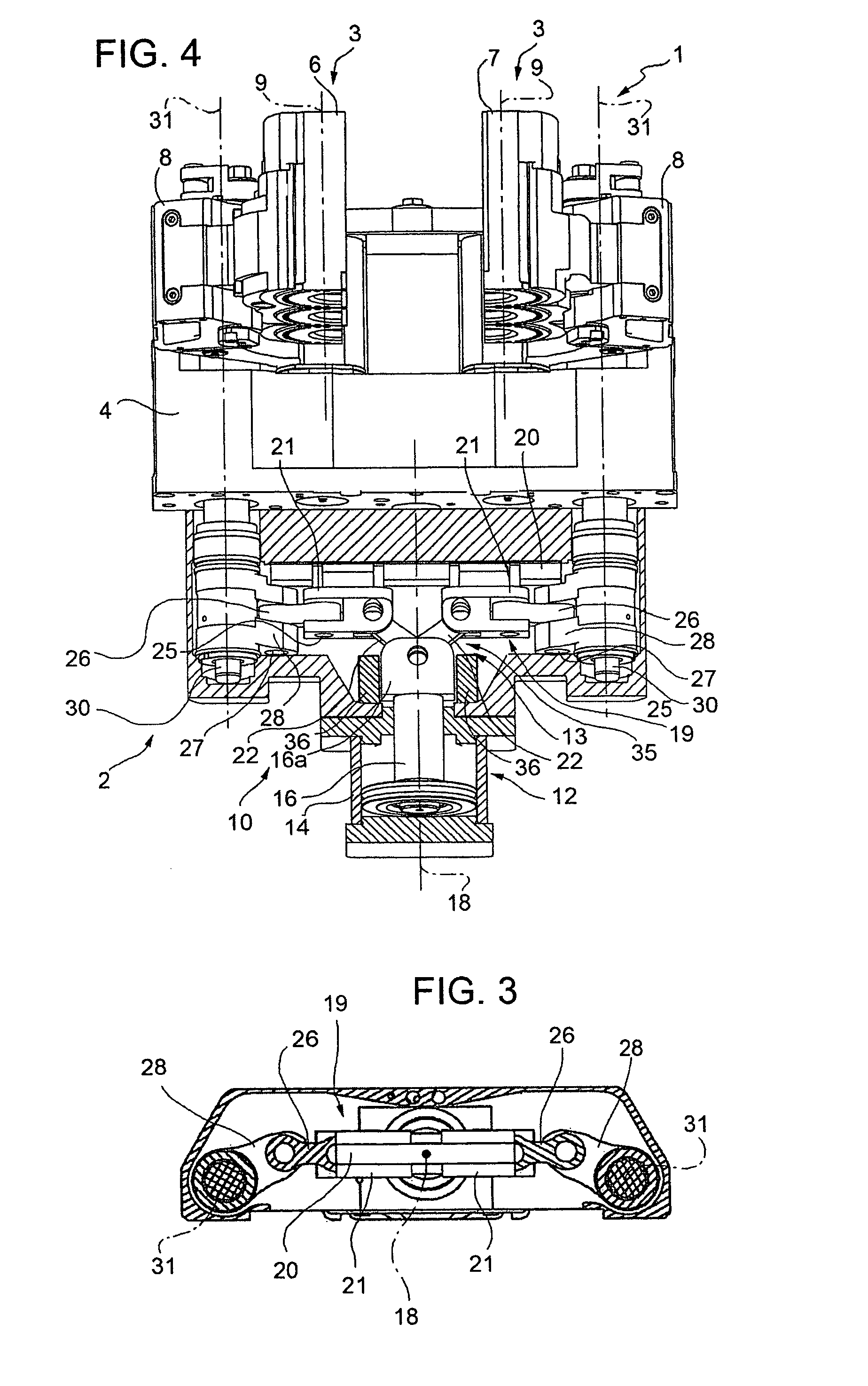
[0018]Number 1 in FIGS. 1 and 2 indicates as a whole a machine for forming glass items (not shown). Machine 1, commonly known as an I.S. machine, comprises a hollow bottom supporting structure 2, only shown partly; and a mold assembly 3, in turn comprising a connecting and supporting frame 4 locked in a fixed position to hollow structure 2, and two half-molds 6 and 7.

[0019]Each half-mold 6, 7 is connected to frame 4 by a respective arm 8, which is connected in known manner to relative half-mold 6, 7 on one side, and is hinged to frame 4, on the other side, by a hinge pin extending coaxially with a respective fixed hinge axis 9.

[0020]Arms 8 are rotated, with respect to frame 4, in opposite directions about respective fixed hinge axes 9, and by a mold opening / closing group 10, between a closed position, in which half-molds 6, 7 define an item molding cavity (FIG. 1), and an open position, in which half-molds 6, 7 are parted to permit withdrawal of the item (FIG. 2).

[0021]As shown in F...


PUM

PropertyMeasurementUnit
right angleaaaaaaaaaa
shapeaaaaaaaaaa
sizeaaaaaaaaaa

Abstract

In a machine for forming glass items, a mold having two half-molds movable between a closed forming position and an open extraction position by a mold opening / closing group is provided. The mold includes two handling arms, each connected to a respective half-mold, which are rotated about respective fixed hinge axes by a single linear actuator. The mobile member translates in a direction parallel to the fixed hinge axes, and is connected to the handling arms by a mechanical transmission having a respective guide-and-slide assembly for each handling arm.

Description

[0001]The present invention relates to a molds opening / closing group of a machine for forming glass items.BACKGROUND OF THE INVENTION[0002]Glass items are known to be formed using what are commonly known as I.S. forming machines, which comprise a number of side by side forming sections, each for producing a respective succession of glass items.[0003]Each forming section comprises a rough mold, normally with a row of adjacent cavities, each for receiving a glass gob and forming a respective semifinished item. Each semifinished item is fed in a forming direction and transferred, by an inverter, to a finish mold, in which it is worked further to obtain the desired finish item, which is then extracted from the mold and unloaded.[0004]The rough mold and finish mold each comprise two half-molds movable with respect to each other between a closed position and an open position.[0005]The half-molds are moved between the open and closed positions by a mold opening / closing group, which compris...

Claims


Application Information

Patent Timeline
Patent Type & Authority Patents(United States)
IPC IPC(8): C03B9/34C03B9/353C03B9/44
CPCC03B9/3532
Inventor BALBI, MARIOBAROLO, MAURIZIOOSTORERO, MARCELLO
Owner BOTTERO SPA
Learn More