Pool cage beam brush

a technology of beam brush and cage, which is applied in the field of cleaning and brushing, can solve the problems of crew of several workers, surface mildew, dirt collection,

Inactive Publication Date: 2012-02-21
RUH II GARY ROBERT
View PDF24 Cites 27 Cited by
  • Summary
  • Abstract
  • Description
  • Claims
  • Application Information

AI Technical Summary

Problems solved by technology

The inventor has found that the surfaces on such cages are subject to mildew as well as dirt collection.
Heretofore, the cleaning of these surfaces has required power washing, which, in turn, often requires a crew of several workers.
The cleaning operation can be messy, expensive and time consuming if carried out by power washing.
The power washing can also damage paint on the structure thereby requiring the owner to incur still further costs in both time and money to repaint damaged areas.

Method used


Image

  • Pool cage beam brush

Examples


Embodiment Construction

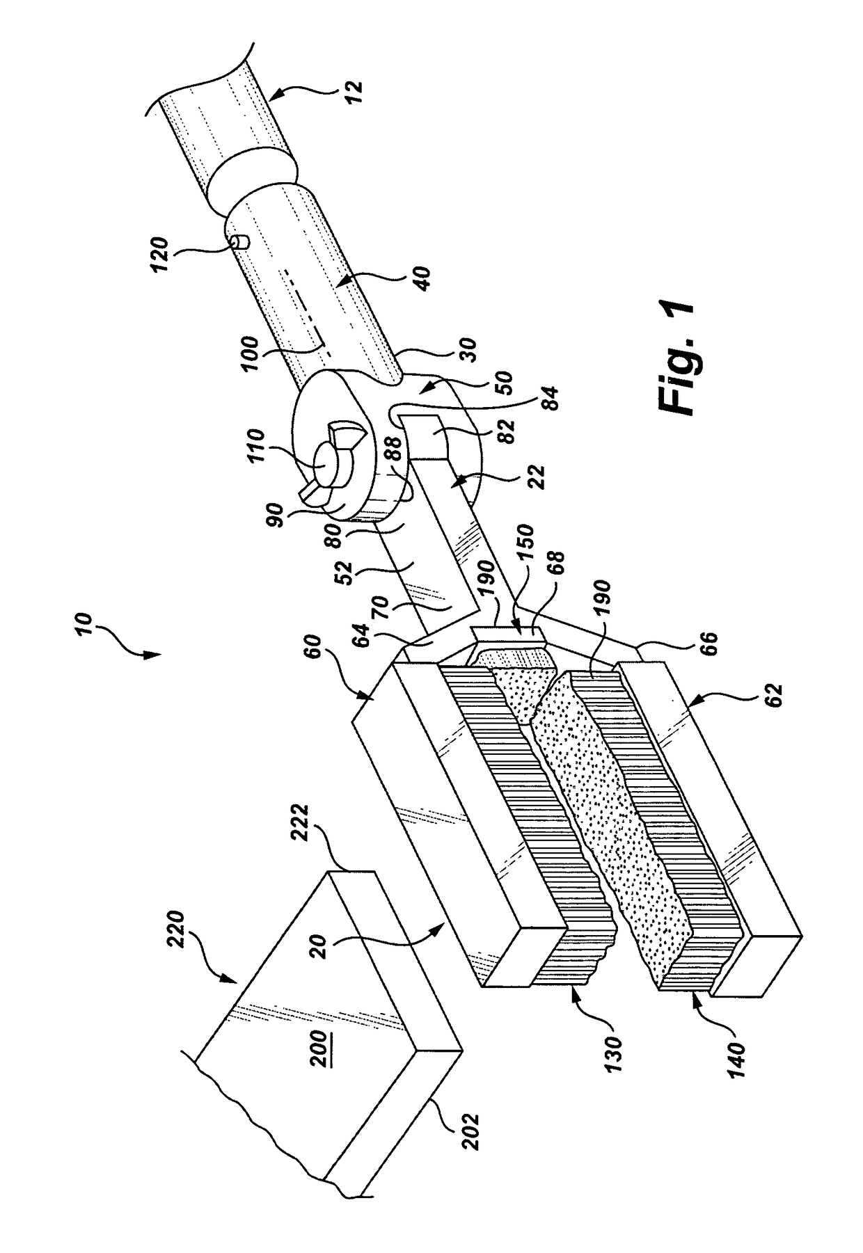
[0010]Referring to the FIGURE, it can be understood that the present invention is embodied in a brush implement 10 that can be releasably mounted on a distal end of a pool broom 12 for use in cleaning surfaces of beams used in a pool cage to prevent dirt, mildew and other undesired elements from building up on those surfaces.

[0011]Brush 10 includes a head section 20 connected at a proximal end 22 thereof to a distal end 30 of a support section 40 by a swivel joint 50. Head section 20 is Y-shaped and includes a base section 52 on which is mounted two spaced-apart legs 60 and 62. Legs 60 and 62 are attached to base section 52 by connecting sections 64 and 66 respectively and have a landing section 68 located therebetween adjacent to distal end 70 of the base section.

[0012]Base section 52 has a proximal end 80 which has a circular attachment section 82 thereon. Section 82 has a first surface 84 on which knurling or teeth (not visible in the FIGURE) are positioned for engagement with co...


PUM


Abstract

A brush device can be releasably attached to a distal end of a pool broom and has a plurality of strategically placed brushes which brushingly engage the surfaces of the beams of a pool cage to clean those surfaces. The brushes are mounted on a head that can be angularly adjusted so the brushes will engage the cage surfaces in a manner which is conducive to thorough cleaning of those surfaces. The brushes are releasably mounted so they can be removed for cleaning or replacement.

Description

TECHNICAL FIELD OF THE INVENTION[0001]The present invention relates to the general art of cleaning and brushing, and to the particular field of cleaning implements for special applications.BACKGROUND OF THE INVENTION[0002]Many swimming pools are enclosed by a screened swimming pool cage which is structurally formed of box or rectangular section aluminum tubing. Screened swimming pool cages, lanai structures and the like are generally fabricated using rectangularly sectioned channel members formed of thin wall aluminum extrusions. These channel members include several surfaces and longitudinal spaced grooves on at least one surface, and typically on opposing surfaces which are coextensive with the channel member and are utilized primarily on an outwardly facing surface to supportively engage with screening enclosure material held in place with an elastomeric bead being forced into each groove with an edge of the screen material.[0003]Such a screen enclosure typically includes a plura...

Claims


Application Information

Patent Timeline
Patent Type & Authority Patents(United States)
IPC IPC(8): A46B9/02A46B15/00
CPCA46B5/0012A46B5/0075A46B5/0083B08B1/008E04H4/1609A46B2200/3073
Inventor RUH, II, GARY ROBERT
Owner RUH II GARY ROBERT
Why Eureka
Try Eureka