Multi-purpose firefighting tool

a multi-purpose, firefighting technology, applied in the direction of manufacturing tools, lifting devices, crowbars, etc., can solve the problems of few practical, useable, handheld firefighter tools, difficult, unpredictable situations, etc., and achieve the effect of convenient utilization and better leverag

Inactive Publication Date: 2012-03-06
TYGH DANIEL P
View PDF8 Cites 16 Cited by
  • Summary
  • Abstract
  • Description
  • Claims
  • Application Information

AI Technical Summary

Benefits of technology

[0002]The object of the present invention is to overcome the disadvantages and limitations of prior manually held firefighting tools by providing a single tool which is configured with the most desirable and practical features of existing tools. The firefighting tool of the present invention combines the aspects of ceiling hooks, drywall hooks, duckbill padlock breakers, pry bars, battering rams, wall picks, hay drags, rubbish rakes, spikes, baling hooks, clawed tools, and others. The subject tool is a striking, pushing, pulling, and prying tool all in one. Its claw, spike, and adz-like elements provide for new prying configurations, not found in other forcible entry tools. The length of the tool allows for better leverage and can easily be utilized by two firefighters for heavy prying, pulling and battering. Its extreme versatility allows the firefighter to carry a single tool with many functions, as opposed to the need for carrying many different types of tools.

Problems solved by technology

Firefighters often face dangerous, difficult, and unpredictable situations which require the use of manually held firefighting tools.
However, there are very few practical, useable, handheld firefighter tools which are configured to perform multiple tool functions and none which have the versatility to be used in most tool related circumstances a firefighter will encounter.

Method used


Image

  • Multi-purpose firefighting tool
  • Multi-purpose firefighting tool
  • Multi-purpose firefighting tool

Examples


Embodiment Construction

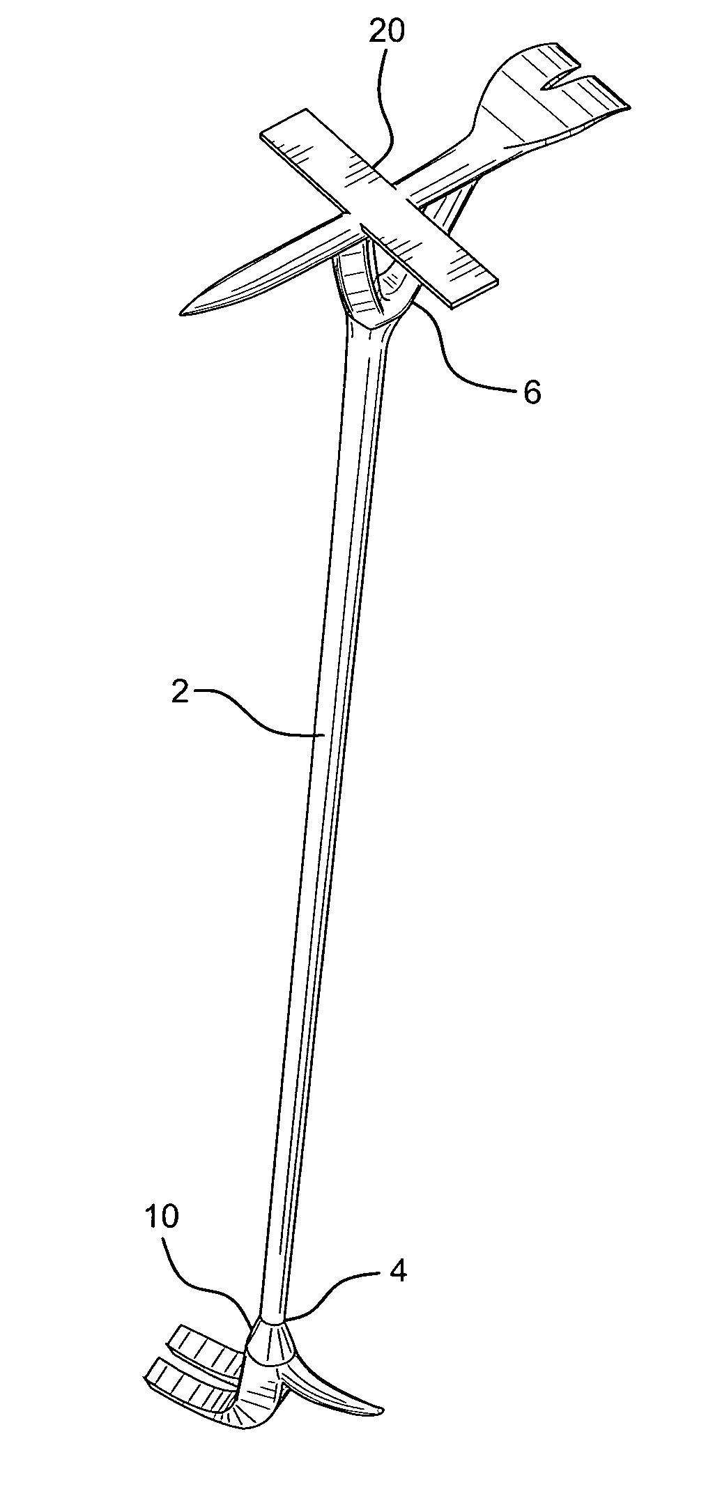
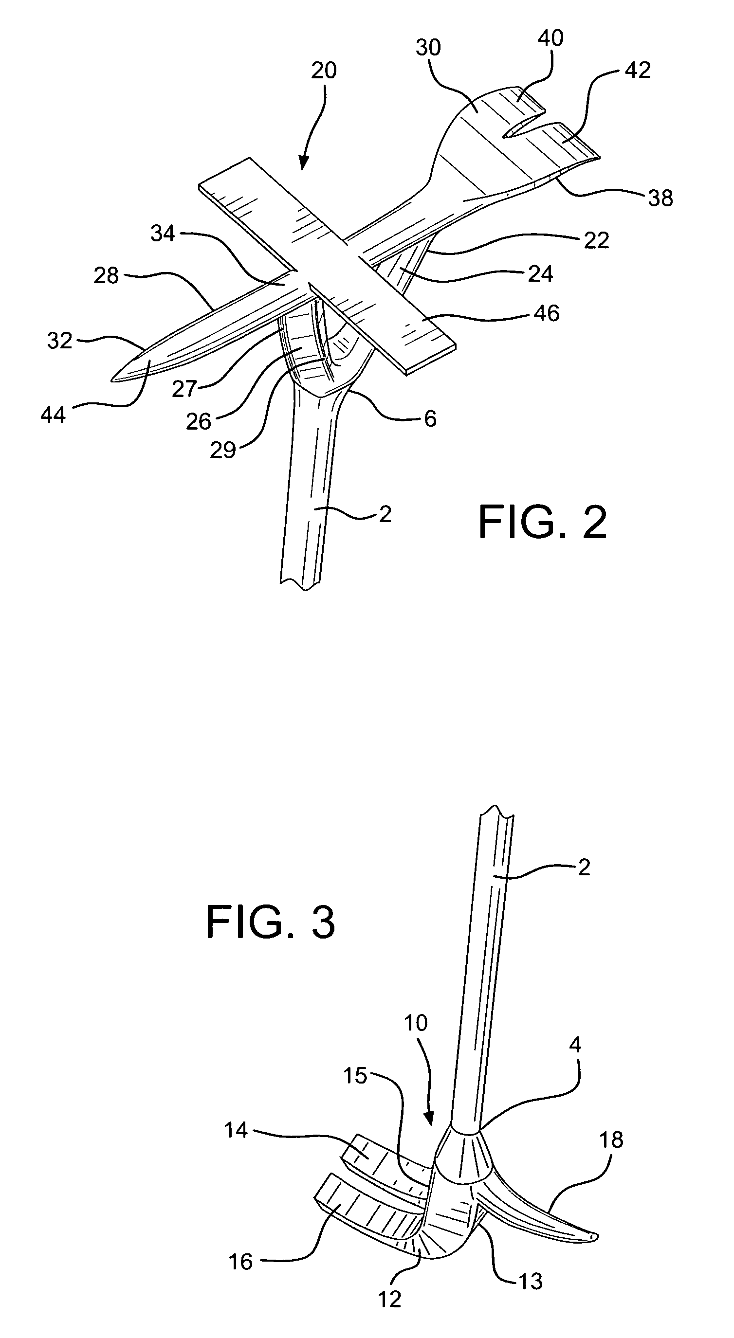
[0014]Firefighting tool 1 of the present invention comprises elongated rigid staff section 2 having opposing ends 4 and 6. Longitudinal axis 8 extends through the length of staff 2. It is anticipated that staff section will be approximately four to five feet in length. However, the invention is not to be restricted to this dimension.

[0015]Operative working member 10 is located on tool 1 at end 4 of staff section 2. Working member 10 comprises claw element 12 having arcuate arms 14 and 16. Claw element 12 protrudes substantially perpendicularly out from working member 10 and staff 2 in one direction, perpendicular to longitudinal axis 8, at approximately a 90° angle. Claw element 12 comprises substantially flat striking surfaces 13 and 15. Curved spike element 18 protrudes out from the other side of working member 10 and staff section 2 in the opposite direction of claw element 12, perpendicular to longitudinal axis 8, at approximately a 90° angle.

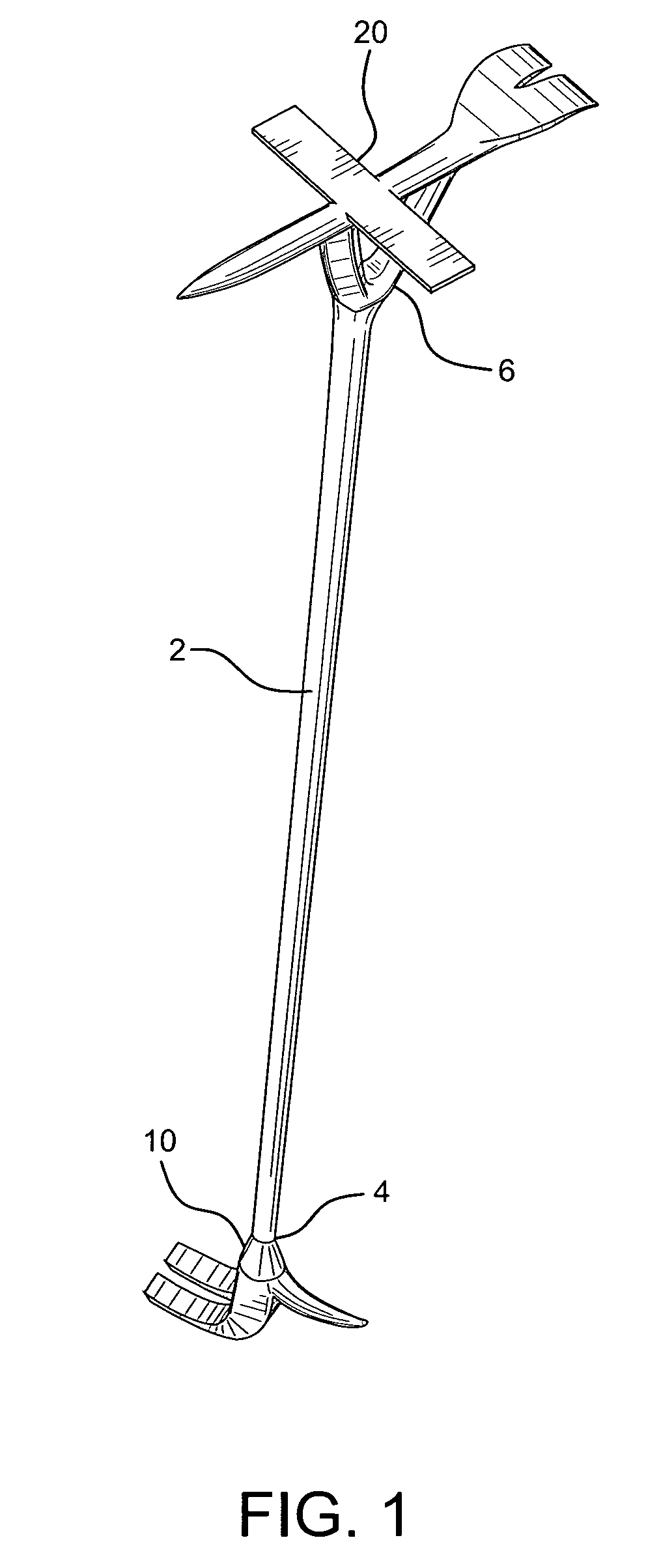
[0016]Operative working member 20 is...


PUM


Abstract

A manually held firefighting tool has an elongated staff section having a first working member at one end and a second working member at the other end. The first working member has a claw element and a spike element, each extending perpendicular to the longitudinal axis of the staff section and protruding from the staff section in opposite directions. The second working member extends from the second end of the staff section and has a U-shaped yoke element supporting an arcuate cross bar element positioned parallel to the longitudinal axis of the staff section. The second working member has its own claw element at one end and a spike element at the other end. A flat bar element is affixed perpendicularly to the cross bar element between its two ends. The firefighting tool is configured to be used in a variety of firefighting applications, allowing the firefighter to carry a single tool rather than a multitude of tools performing different functions.

Description

BACKGROUND OF THE INVENTION[0001]Firefighters often face dangerous, difficult, and unpredictable situations which require the use of manually held firefighting tools. Normally, several different types of tools are required to address the need to manually ventilate spaces, gain entry into burning structures or vehicles, pry or batter down doors, walls, and windows, penetrate locks and gates, rescue individuals, and perform a myriad of other tasks. Various tools are used for these purposes e.g. Halligan bars, pry axes, crowbars, flat bars, pike poles, padlock breakers, and others. However, there are very few practical, useable, handheld firefighter tools which are configured to perform multiple tool functions and none which have the versatility to be used in most tool related circumstances a firefighter will encounter.SUMMARY OF THE INVENTION[0002]The object of the present invention is to overcome the disadvantages and limitations of prior manually held firefighting tools by providing...

Claims


Application Information

Patent Timeline
Patent Type & Authority Patents(United States)
IPC IPC(8): B66F15/00B25C11/00
CPCA62B3/005
Inventor TYGH, DANIEL P.
Owner TYGH DANIEL P
Why Eureka
Try Eureka