
Golf putter head including a cantilevered alignment aid

a golf putter and alignment aid technology, applied in golf clubs, sport equipment, golf, etc., can solve the problems of pushed or pulled putts, adding more strokes to the round of golfers, and many golfers struggling to perform the task consistently and successfully

Active Publication Date: 2012-03-06
WILSON SPORTING GOODS
View PDF48 Cites 64 Cited by
  • Summary
  • Abstract
  • Description
  • Claims
  • Application Information

AI Technical Summary

Benefits of technology

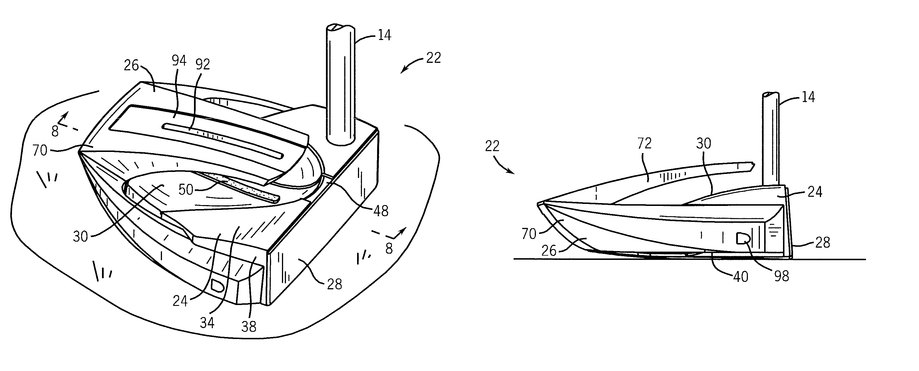
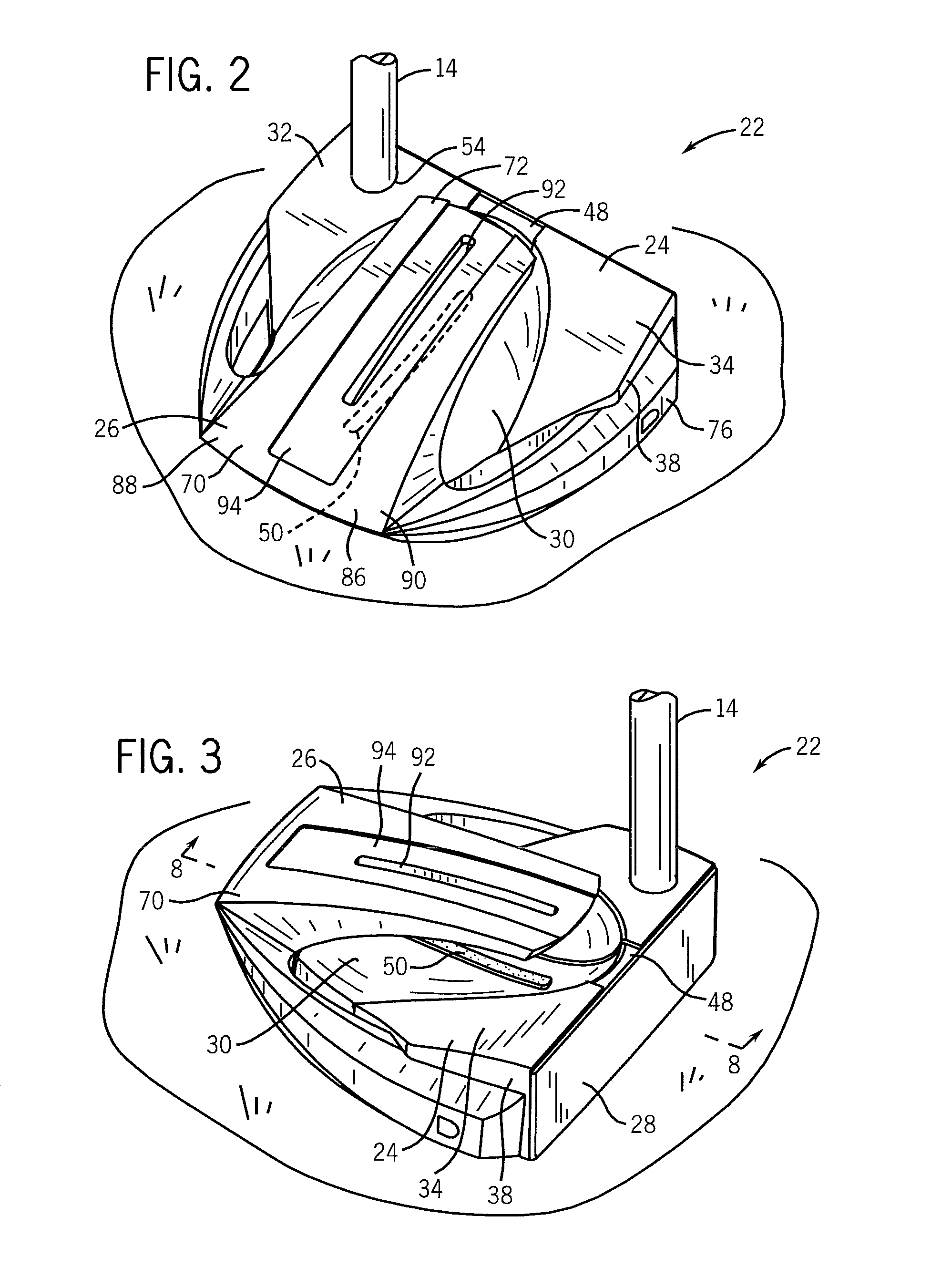
The present invention provides a putter head for a golf club with a fore body and an aft body. The fore body has a planar front strike face, heel side wall, toe side wall, rear wall, top surface, and a sightline. The aft body has a rear main portion and an overhang. The overhang has an elongate slot that contacts only the rear portion of the putter head and extends over a majority of the surface area of the sightline when placed on a horizontal surface. This invention improves the accuracy and consistency of the golfer's swing.

Problems solved by technology

The putting stroke may seem like the simplest swing in golf to perform, but many golfers struggle to perform the task consistently and successfully.
However, if a golfer places his or her eyes inside or outside of the aim line of putt, undesirable alignment angles result, which can lead to pushed or pulled putts.
The failure of a putter to consistently align his or her eyes over the target line leads to difficulty in hitting puts on a consistent line, and therefore adds more strokes to a golfer's round due to failed putt attempts.
Such incorrect alignment is common for many golfers and not easy to self-diagnose.
Sightlines vary in length, width, shape and style, but typically do not assist a golfer in properly aligning his or her eyes over the putter and the target line of the putt.
Further, many existing putters provide poor weight distribution which can lead to inadvertent and undesirable shifting or misalignment of the strike face of the putter during the putting stroke, which can also lead to missed putts and / or pushed or pulled putts.

Method used


Image

  • Golf putter head including a cantilevered alignment aid
  • Golf putter head including a cantilevered alignment aid
  • Golf putter head including a cantilevered alignment aid

Examples


Embodiment Construction

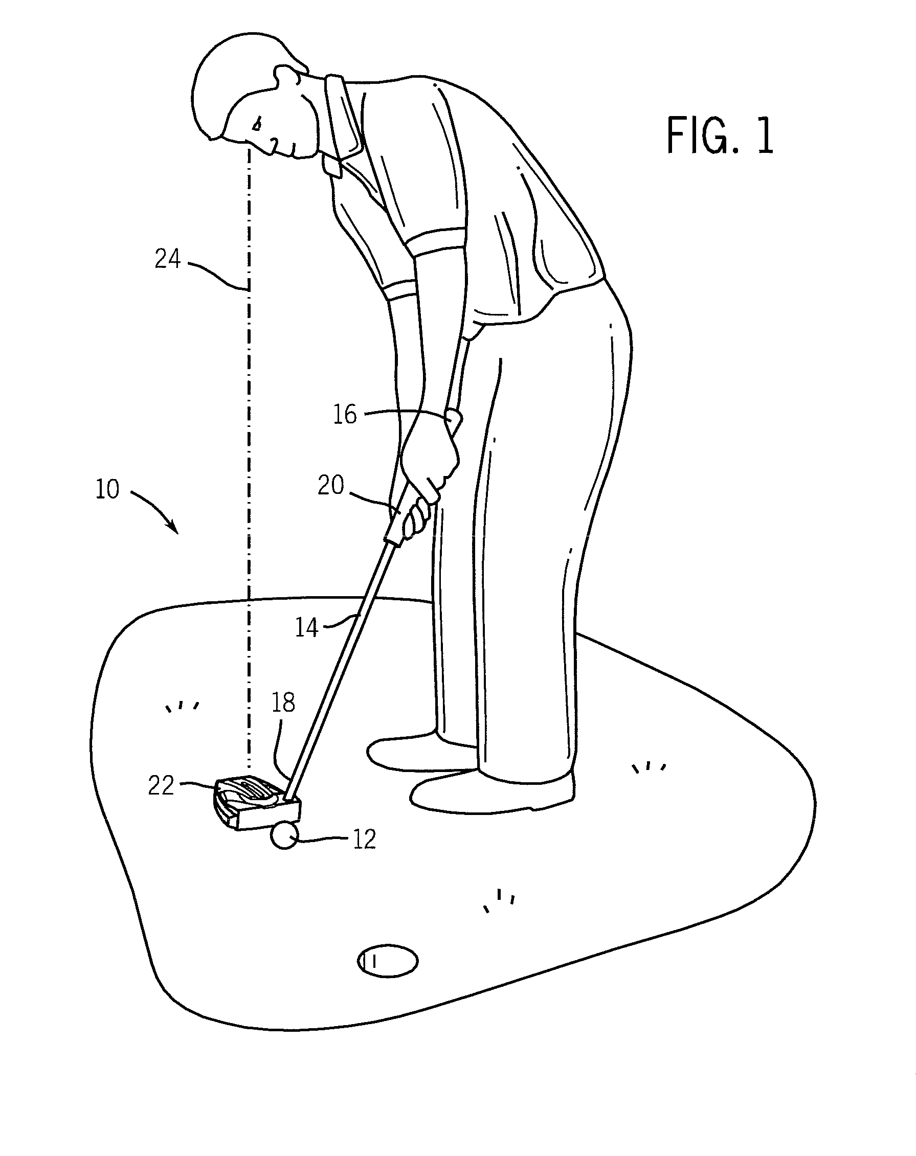
[0023]Referring to FIG. 1, a putter is indicated generally at 10. The putter 10 is an elongate implement configured for stroking or putting a golf ball 12 and includes a golf shaft 14 having a butt end 16 and a tip end 18, a grip 20 coupled to the butt end 16, and a putter club head 22 (or putter head) coupled to the tip end 18. The putter 10 of the preferred embodiment is configured for use by a right-handed golfer. The putter can be also be configured for use by a left-handed golfer. The present invention facilitates the golfer's ability to properly align himself or herself over the club head 22 prior to and during the execution of a putting stroke. Axis 24 is vertically aligned to indicate that the eyes of the golfer are properly aligned over the club head 22.

[0024]The club head 22 is a generally planar body that is coupled to the shaft 14. Preferably, the club head 22 is affixed to the shaft 14 with an epoxy adhesive. A ferrule (not shown) can be used to generally cover a portio...


PUM


Abstract

A putter head including a fore body and an aft body. The fore body includes a planar front strike face, heel and toe side walls, a rear wall, a top surface and a generally planar sole. The top surface includes a sight line. The sight line extends along a first plane that is perpendicular to the strike face and to the sole, and is substantially evenly spaced from the heel and toe side walls. The aft body is coupled to the fore body and includes a rear main portion and an overhang. The rear main portion is engaged to the rear wall of the fore body, and has a central region positioned between first and second end regions. The overhang forwardly extends from the central region. The overhang includes an elongate slot extending along the first plane, and is positioned over at least a portion of the sight line.

Description

RELATED U.S. APPLICATION DATA[0001]The present invention claims the benefit of the filing date under 35 U.S.C. §119(e) of U.S. Provisional Patent Application Ser. No. 61 / 313,581, filed on Mar. 12, 2010, which is hereby incorporated by reference in its entirety.FIELD OF THE INVENTION[0002]The present invention relates generally to a club head for a golf club. In particular, the present invention relates to a head of a putter including a cantilevered alignment aid.BACKGROUND OF THE INVENTION[0003]Of all the clubs used by golfers during a round: drivers, irons, wedges, hybrids and putters; the putter is the club that is used the most. In one Industry study, putting accounting for over 43 percent of the average golfer's strokes during a round of golf. See Science and Golf, Proceedings of the World Scientific Congress of Golf, “An Analysis of Eye and Club Face Alignment at Address in Putting” by James MacKay, OnePutt Enterprises, Inc. Accordingly, the putter is the most often used club i...

Claims


Application Information

Patent Timeline
Patent Type & Authority Patents(United States)
IPC IPC(8): A63B69/36A63B53/04
CPCA63B53/0487A63B2053/0441A63B2053/0437A63B2053/0416A63B2069/3682A63B53/0416A63B53/0437A63B53/0441A63B69/3682
Inventor TRYNER, ANDREW K.THIEL, DOUGLAS J.THURMAN, ROBERT T.PERGANDE, JON C.
Owner WILSON SPORTING GOODS
Learn More