Anti-splay medical implant closure with multi-surface removal aperture

a technology of medical implants and apertures, applied in the direction of prosthesis, osteosynthesis devices, screws, etc., can solve the problems of implant special problems, difficult to solve, and the surgeon installing the implants a number of problems, and achieve the effect of low or minimal profile, enhanced setting engagement of the closure body, and economical manufacturing

Active Publication Date: 2012-03-06
JACKSON
View PDF449 Cites 46 Cited by
  • Summary
  • Abstract
  • Description
  • Claims
  • Application Information

AI Technical Summary

Problems solved by technology

Medical implants present a number of problems to both surgeons installing implants and to engineers designing them.
These are normally conflicting goals, and often difficult to resolve.
One particular type of implant presents special problems.
While open headed devices are often necessary and often preferred for usage, there is a significant problem associated with them.
The closure can be of a slide in type, but such are not easy to use.
Such nuts prevent splaying of the arms, but nuts substantially increase the size and profile of the implant which is not desirable.
However, threaded plugs have encountered problems also in that they produce radially outward directed forces that lead to splaying or spreading of the tops of the arms or at least do not prevent splaying caused by outside forces that in turn loosen the implant.
But, as noted above, conventional V-shaped threaded plugs tend to splay or push the arms radially outward upon the application of a significant amount of torque, which ends up bending the arms sufficiently to allow the threads to loosen or disengage and the closure to fail.
This had the unfortunate effect of substantially increasing the weight and the profile of the implant, which was undesirable.
However, the linear surfaces still allow sideways slippage, if other forces are applied to the arms.
The threads can be distorted or bent by forces exerted during installation.
Therefore, while these types of threadforms are designed to not exert radial forces during installation, at most such threadforms provide an interference or frictional fit and do not positively lock the arms in place relative to the closure plug.
That is, as the surgeon tries to start the threaded plug into the threaded receiver, the thread on the plug is inadvertently started in the wrong turn or pass of the thread on one arm.
This problem especially occurs because the parts are very small and hard to handle.
However, the rod is not secure relative to the bone screw or other implant and the implant fails to function properly.
However, strong and secure are somewhat divergent goals from the goals of lightweight and low profile.

Method used


Image

  • Anti-splay medical implant closure with multi-surface removal aperture
  • Anti-splay medical implant closure with multi-surface removal aperture
  • Anti-splay medical implant closure with multi-surface removal aperture

Examples


Embodiment Construction

[0032]As required, detailed embodiments of the present invention are disclosed herein; however, it is to be understood that the disclosed embodiments are merely exemplary of the invention, which may be embodied in various forms. Therefore, specific structural and functional details disclosed herein are not to be interpreted as limiting, but merely as a basis for the claims and as a representative basis for teaching one skilled in the art to variously employ the present invention in virtually any appropriately detailed structure.

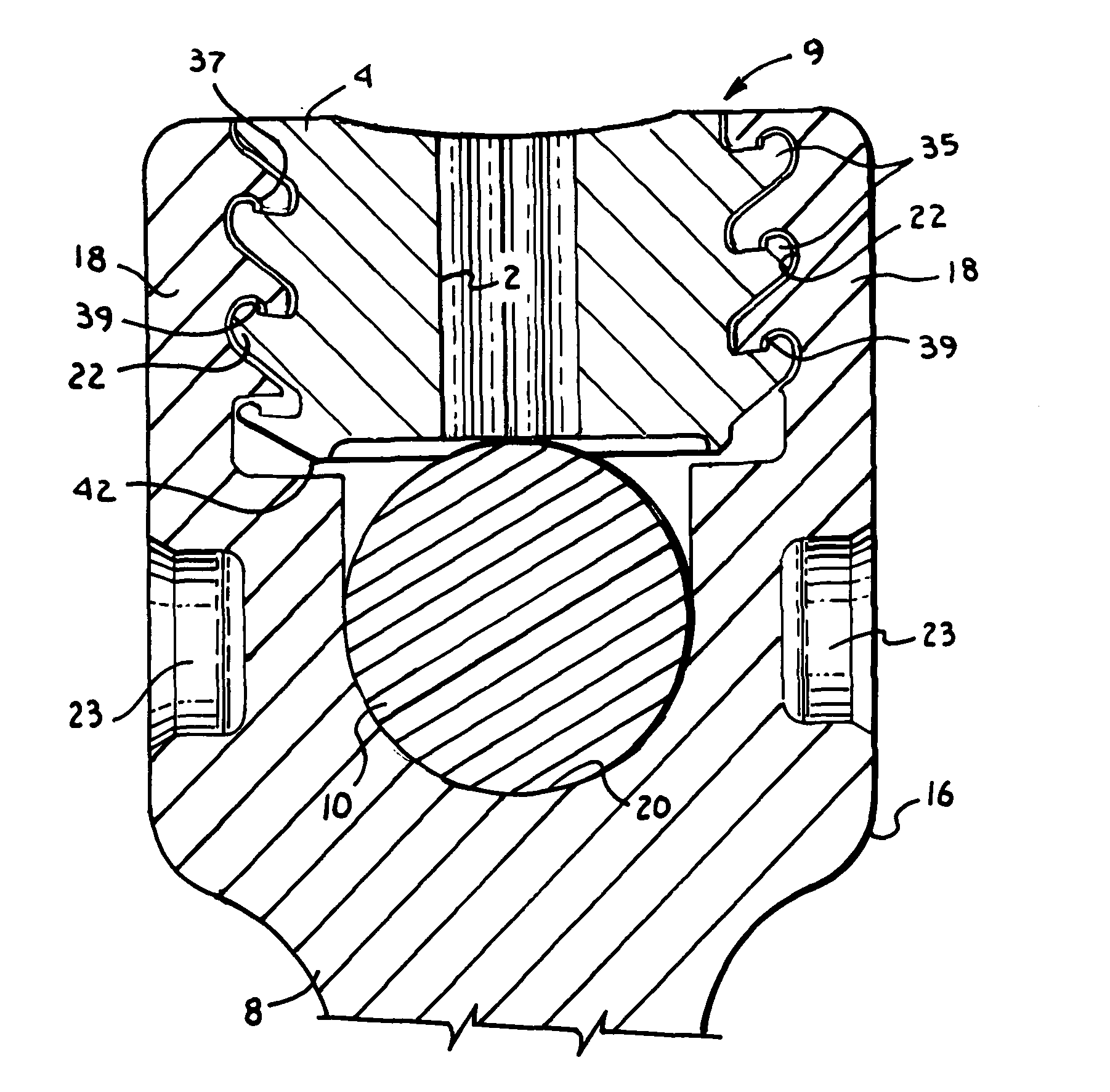
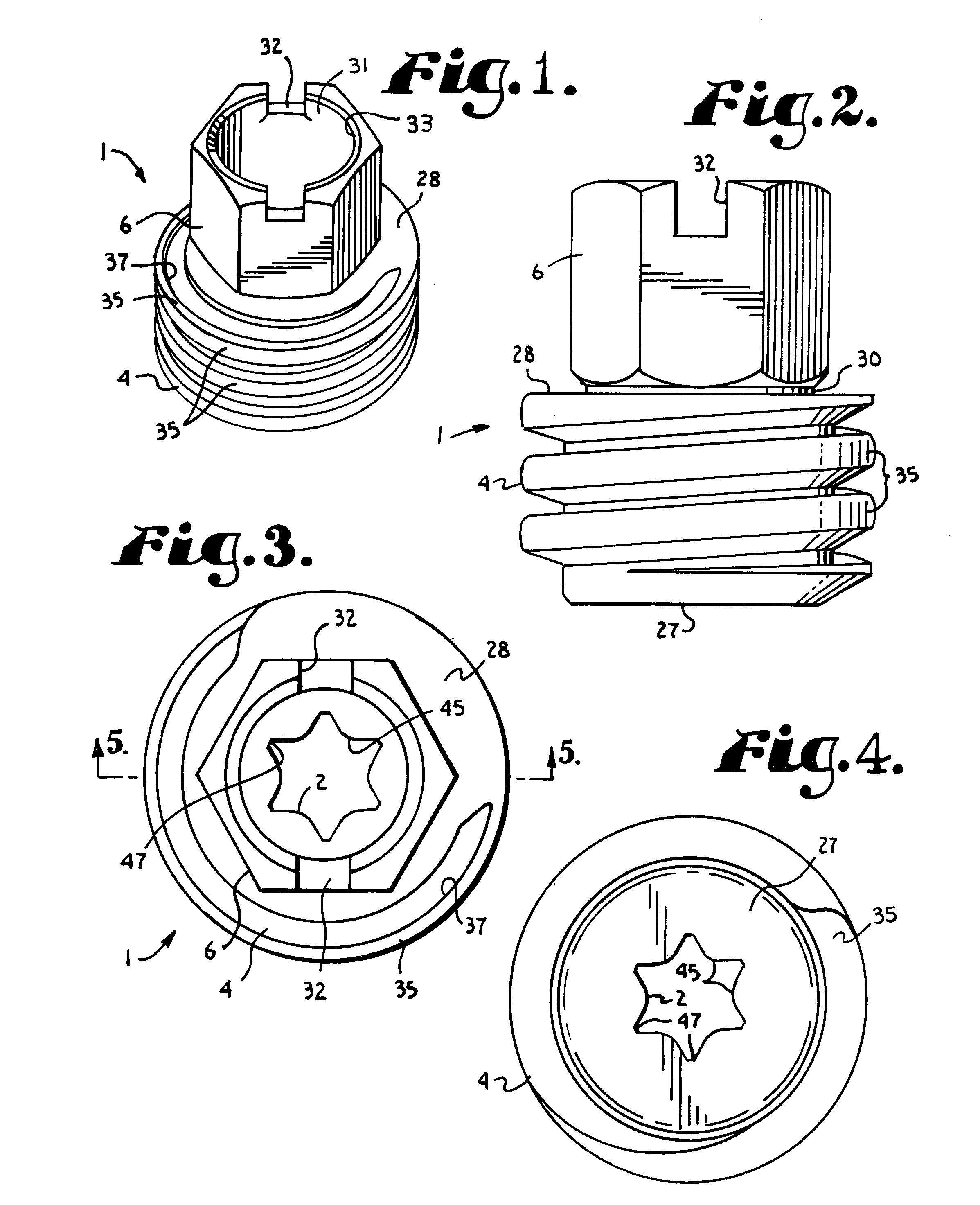
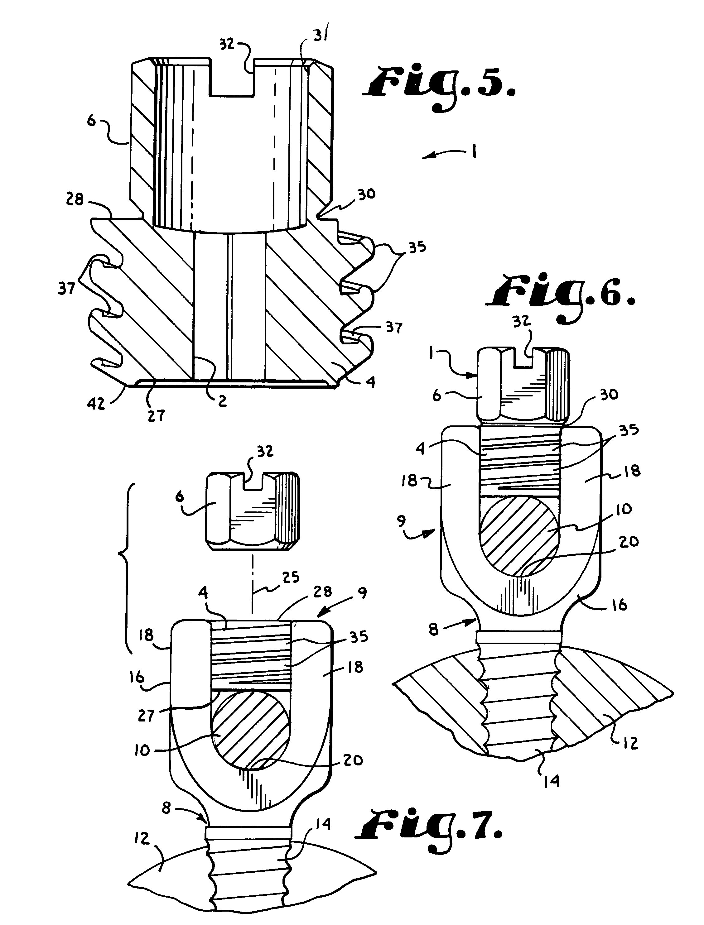
[0033]Referring to the drawings in more detail, the reference numeral 1 generally designates an anti-splay closure with a multi-surfaced aperture, such as a multi-lobular aperture 2. The closure 1 generally includes a body 4 and a breakaway installation head 6. The body 4 is used in cooperation with an open headed bone implant screw 8 (FIGS. 6 and 7) to form an implant anchor assembly 9 to secure or anchor a spinal fixation member or rod 10 with respect to a ...


PUM


Abstract

An anti-splay closure with a multi-surfaced aperture, such as a multi-lobular socket, includes a cylindrical body with an external, continuous, helically extending anti-splay guide and advancement flange and a breakaway installation head.

Description

CROSS-REFERENCE TO RELATED APPLICATION[0001]This is a continuation of co-pending U.S. patent application Ser. No. 10 / 783,889, filed Feb. 20, 2004 for ANTI-SPLAY MEDICAL IMPLANT CLOSURE WITH MULTI-SURFACE REMOVAL APERTURE and this is also a continuation-in-part of U.S. patent application Ser. No. 10 / 236,123, filed Sep. 6, 2002 for HELICAL WOUND MECHANICALLY INTERLOCKING MATING GUIDE AND ADVANCEMENT STRUCTURE, which is now U.S. Pat. No. 6,726,689.BACKGROUND OF THE INVENTION[0002]The present invention is directed to a closure for use in closing between spaced arms of a medical implant and securing a rod to the implant. In particular, the closure includes a non-circular multi-surfaced or multi-lobular internal bore for improved engagement by a complementary shaped tool for purposes of removal and an interlocking helical guide and advancement structure that prevents splaying of upper ends of walls of the implant within which the closure is placed away from an axis of rotation of the clos...

Claims


Application Information

Patent Timeline
Patent Type & Authority Patents(United States)
IPC IPC(8): A61B17/70A61B17/00A61B17/56A61B17/86A61B19/00F16B23/00F16B31/02F16B33/02F16B35/04
CPCA61B17/683A61B17/7032F16B23/0092F16B31/021F16B35/047A61B17/7076A61B2017/8655A61B2019/307F16B23/003F16B33/02A61B2090/037
Inventor JACKSON, ROGER P.
Owner JACKSON
Why Eureka
Try Eureka